Acquired immunodeficiency syndrome diagnosis multichannel microfluidic chip apparatus containing hydrophobic substrate

A microfluidic chip and AIDS technology, applied in the field of analysis and testing, can solve the troublesome operation of modifying the inner surface of the PDMS channel, the difficulty of passing fine liquid flow, and other problems that have not been properly solved

Inactive Publication Date: 2018-03-06
葛光奇
View PDF1 Cites 0 Cited by
  • Summary
  • Abstract
  • Description
  • Claims
  • Application Information

AI Technical Summary

Problems solved by technology

[0007] But it's not that simple
[0008] First, this polydimethylsiloxane material, which is referred to by the acronym PDMS, is itself a strongly hydrophobic material, and channels are built on this material. modification operation, then, after the overall assembly is completed, that is, after the cover is covered, because the inner surface of the channel in the structure occupies most of the inner surface of the liquid flow channel, then the inner surface of the PDMS channel is The strong hydrophobicity is the decisive factor, it will make it very difficult for the polar liquid fine flow similar to the aqueous solution to pass through, and its flow resistance is so large that even the general micropump is difficult to push, of course, if the cover sheet is also If you choose to use the PDMS material, then the problems are basically the same, with minor differences; therefore, in the prior art, it is necessary to modify and modify the inner surface of the channel on the PDMS material; then, this is for the PDMS channel Is the modification operation of the inner surface of the channel very troublesome? That's not the problem. What constitutes a serious technical problem is an

Method used


Image

  • Acquired immunodeficiency syndrome diagnosis multichannel microfluidic chip apparatus containing hydrophobic substrate
  • Acquired immunodeficiency syndrome diagnosis multichannel microfluidic chip apparatus containing hydrophobic substrate

Examples


Embodiment Construction

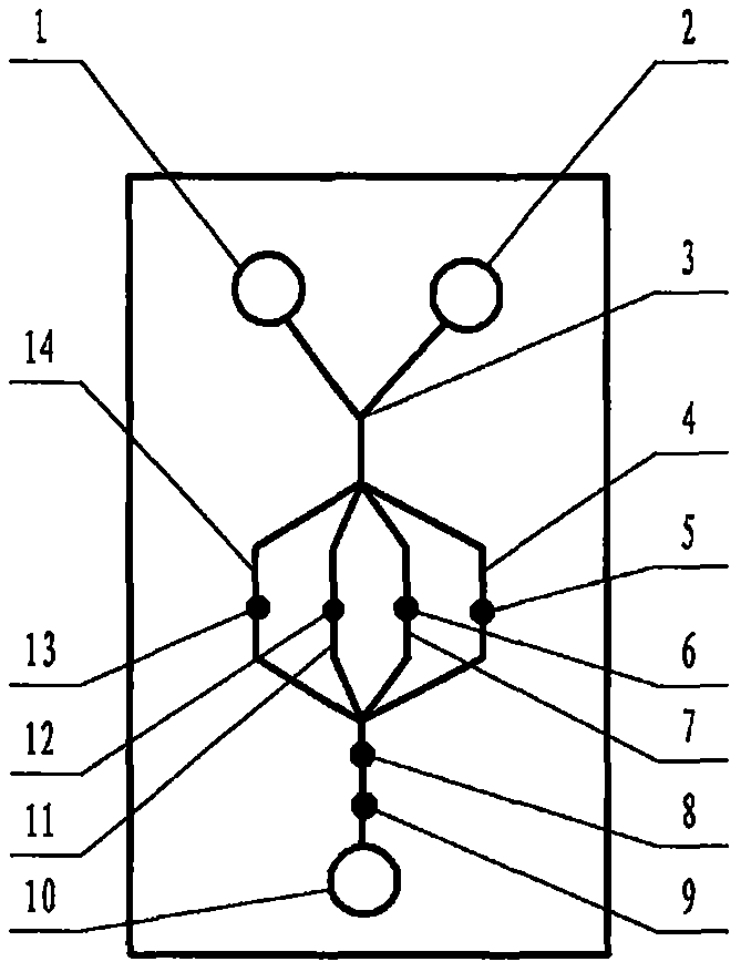
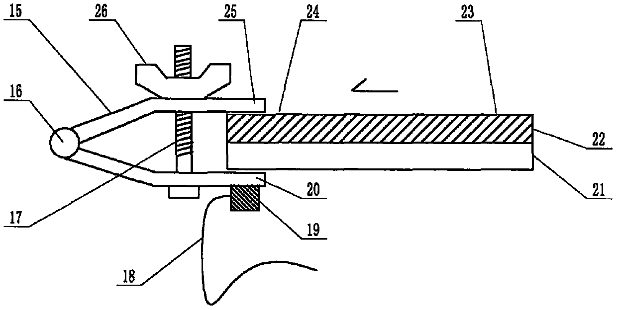
[0074] exist figure 1 and figure 2 In the shown embodiment of the present case, the structure of the device includes a multi-channel microfluidic chip, and the structure of the microfluidic chip includes a substrate 22 and a cover sheet 21 that are attached to each other and installed together. The substrate 22 and the cover sheet 21 are plates or sheets, the surface of the substrate 22 facing the cover sheet 21 contains a channel structure formed by a molding process or an etching process, and the substrate 22 also contains a channel structure that is connected to the groove The window structure is connected to the channel structure and penetrates the substrate through a molding process, an etching process or a simple punching process. The substrate 22 and the cover sheet 21 that are attached to each other are jointly constructed to contain a channel structure and a window structure. A microfluidic chip with a liquid pool structure connected to it, the liquid pools are liqu...


PUM

PropertyMeasurementUnit
Particle sizeaaaaaaaaaa
Diameteraaaaaaaaaa
Lengthaaaaaaaaaa

Abstract

The invention relates to a multi-channel microfluidic chip device for AIDS diagnosis comprising a hydrophobic substrate, which belongs to the field of analysis and testing. There are technical obstacles in making the substrate of the microfluidic chip for AIDS diagnosis with cheap and easy-to-process polydimethylsiloxane (PDMS). The gist of this case is that the substrate is selected from PDMS with an original ecological surface, and the hinged fixture with a micro-ultrasonic transducer is manually fastened and positioned at the position adjacent to the sample liquid flow terminal of the microfluidic chip, so as to The ultrasonic wave induces the sample liquid flow to flow from the sample injection end of the chip along the pipe of the chip to the terminal. The pipe of the chip is filled with micron-sized silicon dioxide particle fillers. The function of the filler includes supporting the inner wall of the pipe, And, a collection of hydrophilic micro-channels is used to compensate the originally hydrophobic channels, and the inner wall of the channel is squeezed and covered to reduce the chance of biomacromolecules in contact with the inner wall.

Description

technical field [0001] The invention relates to a multi-channel microfluidic chip device for AIDS diagnosis comprising a hydrophobic substrate, which belongs to the field of analysis and testing. Background technique [0002] For the background of multi-channel microfluidic AIDS diagnosis technology, please refer to CN 200910151219.0 and other invention patent applications. [0003] As far as the overall overview of microfluidic technology itself is concerned, you can refer to the monograph "Illustrated Microfluidic Chip Laboratory" published by the famous microfluidic expert Mr. Lin Bingcheng not long ago, which has been published by Science Press. The past, present, and future prospects of microfluidic technology, etc., have detailed and long-form discussions that go deep into specific details. [0004] So, let's talk about the key issues of this case. [0005] The basic structure of a microfluidic chip includes a substrate etched with channels and a cover sheet attached...

Claims


Application Information

Patent Timeline
IPC IPC(8): G01N33/569
CPCG01N33/56988
Inventor 李榕生葛宇杰葛光奇蒋剑萍
Owner 葛光奇
Why Eureka
Try Eureka