Oil-gas separation device with impeller

A separation device and impeller technology, which is applied to the lubrication of jet propulsion devices, gas turbine devices, turbine/propulsion devices, etc., can solve the problems of reducing oil return capacity, increased bearing cavity pressure, and poor oil return, etc., to achieve Improve the centrifugal separation effect, enhance the airflow rotation, and improve the effect of connection strength

Active Publication Date: 2021-08-13
AECC HUNAN AVIATION POWERPLANT RES INST
View PDF8 Cites 0 Cited by
  • Summary
  • Abstract
  • Description
  • Claims
  • Application Information

AI Technical Summary

Problems solved by technology

Because the gas needs to overcome the centrifugal force, the flow resistance is relatively large, which will cause the pressure in the bearing chamber to increase. If the bearing chamber adopts the gravity oil return of the lubricating oil, the increase in the bearing chamber pressure will reduce the oil return ability of the lubricating oil, resulting in poor oil return and the generation of lubricating oil. Coking, leakage and other problems

Method used


Image

  • Oil-gas separation device with impeller
  • Oil-gas separation device with impeller
  • Oil-gas separation device with impeller

Examples


Embodiment Construction

[0034] The technical solutions in the embodiments of the present invention will be clearly and completely described below. Obviously, the described embodiments are only some of the embodiments of the present invention, but not all of them. Based on the embodiments of the present invention, all other embodiments obtained by persons of ordinary skill in the art without creative efforts fall within the protection scope of the present invention.

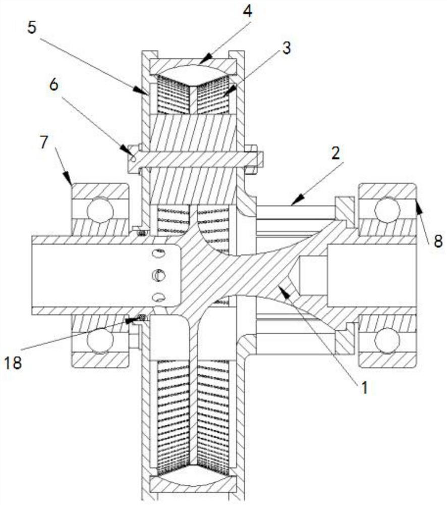
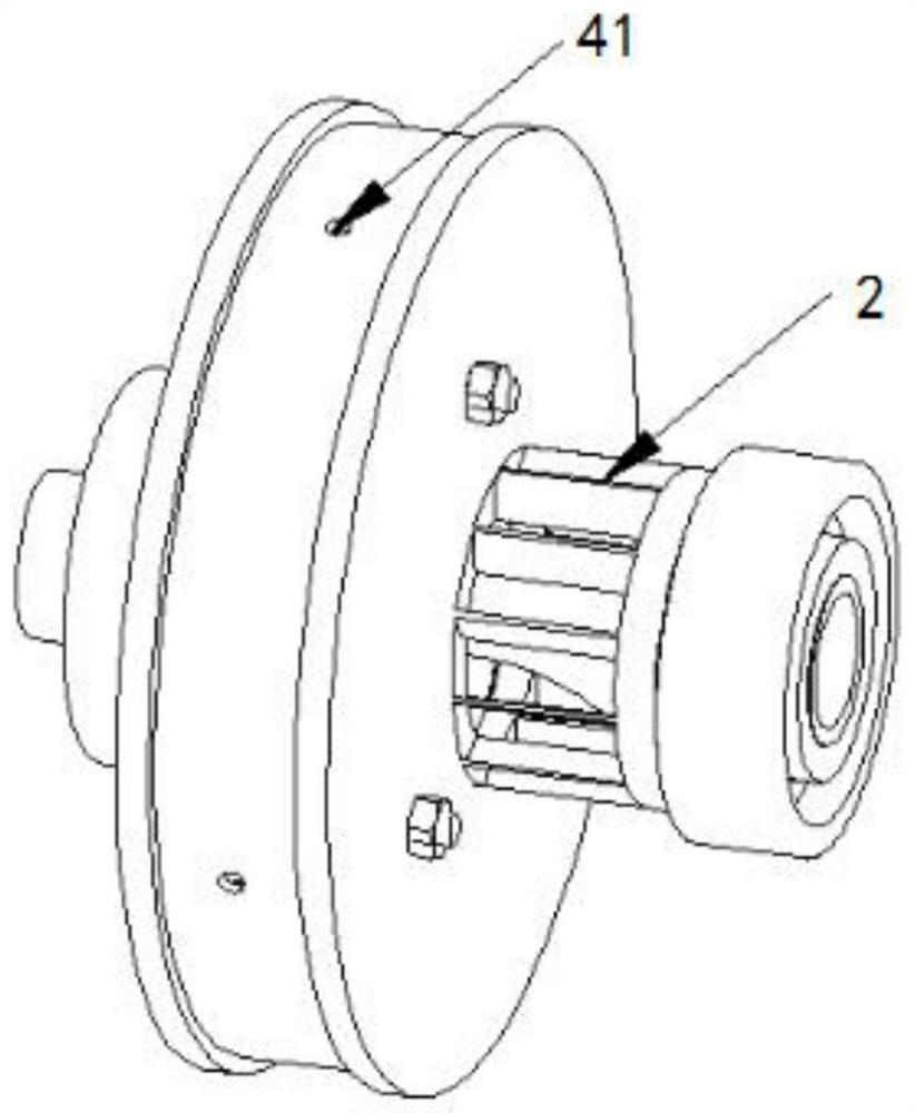
[0035] A kind of oil and gas separation device with impeller, such as Figure 1 to Figure 5 As shown, it includes a central disc 1, an impeller 2, a filter structure 3, an oil collecting ring 4 and two cover plates 5;

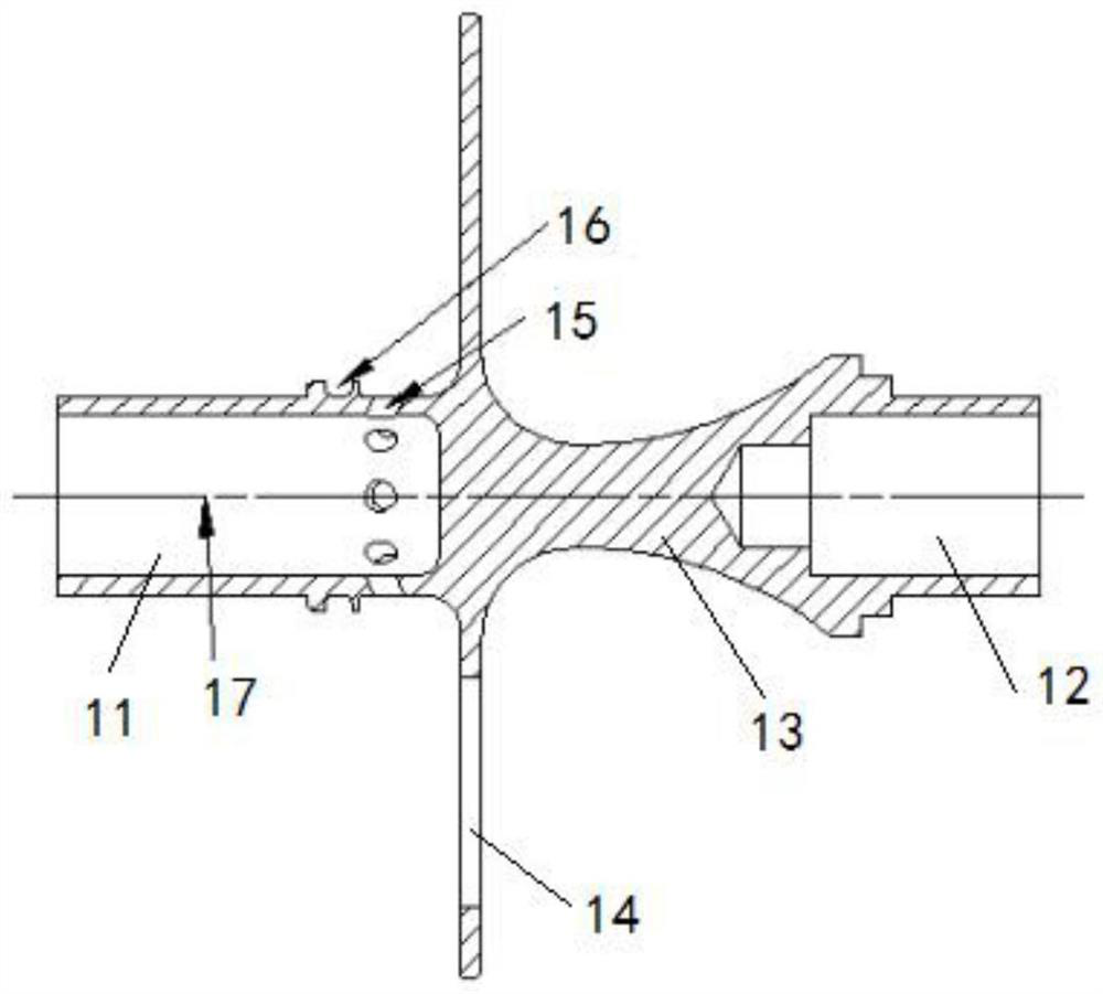
[0036] The central disc 1 includes a first journal 11, a disc portion 14, an arc portion 13 and a second journal 12 arranged in sequence, the first journal 11, a disc portion 14, an arc portion 13 and a second The journal 12 is arranged coaxially and has an integral structure;

[0037] The first support bearing 7 is fix...


PUM


Abstract

The invention discloses an oil-gas separation device with an impeller. The oil-gas separation device comprises a central disc, the impeller, a filter screen structure, an oil collecting ring and two cover plates, wherein the two cover plates and the oil collecting ring form a cylindrical structure with holes formed in the centers of the two bottom surfaces, and the cylindrical structure is fixedly connected to the central disc in a sleeving mode; one end of the impeller communicates with the interior of the cylinder formed by the cover plates and the oil collecting ring, and the other end of the impeller is sealed; and the filter screen structure comprises an annular central mounting part and filter screens fixedly connected to the two sides of the central mounting part, the central mounting part is fixedly connected to the edge of the disc in a sleeving mode, and the sides, away from the central mounting part, of the filter screens are connected with the inner walls of the cover plates in a sealed mode. According to the oil-gas separation device, oil and gas are pressurized and accelerated through the impeller, and flowing resistance can be counteracted; an oil-gas mixture can be filtered twice, so that the oil-gas separation effect is improved; and an airflow channel is provided with a supporting plate, so that airflow rotation can be enhanced, and the centrifugal separation effect is improved.

Description

technical field [0001] The invention belongs to the field of gas turbine engines, and in particular relates to an oil-gas separation device with an impeller. Background technique [0002] In order to prevent the lubricating oil in the bearing cavity from leaking, the aero-engine needs to keep the pressure inside the bearing cavity lower than the pressure outside the bearing cavity. In the low-pressure state in the bearing chamber, the excess oil and gas in the bearing chamber needs to be degreased through the oil-gas separation device and then discharged to the outside. The typical method is to discharge the separated gas to the tail nozzle, and through the ejection of the tail nozzle Enhance gas discharge speed and maintain proper chamber pressure. [0003] The traditional aero-engine oil-gas separation device generally adopts the centrifugal separation method, which uses the different density and centrifugal force of the oil and gas in the oil and gas to throw the oil out...

Claims


Application Information

Patent Timeline
IPC IPC(8): F02C7/06F02C7/00F01D11/06F01D25/00F01D25/16F01D25/18
CPCF02C7/06F02C7/00F01D11/06F01D25/18F01D25/183F01D25/16F01D25/00
Inventor 黄攀张国浩方波罗毅晗刘雨澄
Owner AECC HUNAN AVIATION POWERPLANT RES INST
Why Eureka
Try Eureka