Horizontal compressor

A technology of a compressor and a compression mechanism, applied in the field of compressors, can solve the problems of reducing the energy efficiency and reliability of the compressor, insufficient oil and gas separation of the refrigerant, and reducing the gas guide device, etc., so as to improve the cooling effect, improve the oil and gas separation effect, and improve the The effect of energy efficiency and reliability

Pending Publication Date: 2018-08-14
GUANGDONG WELLING AUTO PARTS CO LTD
View PDF0 Cites 0 Cited by
  • Summary
  • Abstract
  • Description
  • Claims
  • Application Information

AI Technical Summary

Problems solved by technology

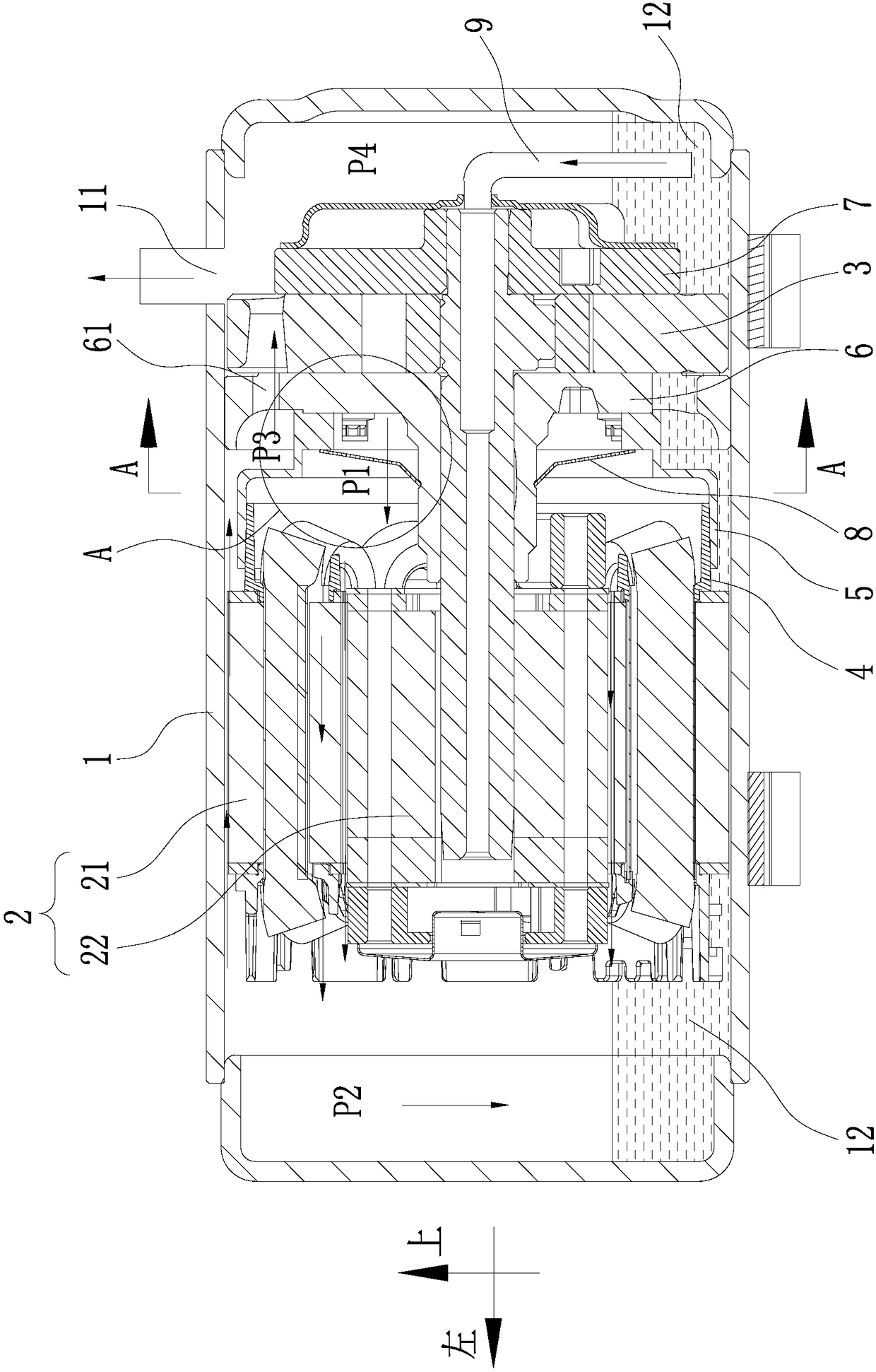
[0003] But at present, due to the limited assembly process, there is often an assembly gap between the gas guiding device and the compression mechanism, so that most of the refrigerant discharged from the compression mechanism no longer flows through the motor, but directly flows away from the assembly gap. In this way, Not only will it reduce the cooling effect of the motor, but it will also prevent the refrigerant from fully separating oil and gas, thereby greatly reducing the role of the gas guide device in reducing the oil output of the compressor, and reducing the energy efficiency and reliability of the compressor

Method used


Image

  • Horizontal compressor
  • Horizontal compressor
  • Horizontal compressor

Examples


Embodiment Construction

[0043] Specific embodiments of the present invention will be described in detail below in conjunction with the accompanying drawings. It should be understood that the specific embodiments described here are only used to illustrate and explain the present invention, and are not intended to limit the present invention.

[0044] It should be noted that, in the case of no conflict, the embodiments of the present invention and the features in the embodiments can be combined with each other.

[0045] In the present invention, unless stated to the contrary, the used orientation words such as "up, down, top, bottom" generally refer to the directions shown in the drawings or refer to the vertical, perpendicular or gravitational directions The terms used to describe the mutual positional relationship of the various components mentioned above.

[0046] The present invention will be described in detail below with reference to the accompanying drawings and examples.

[0047] At present, ...


PUM


Abstract

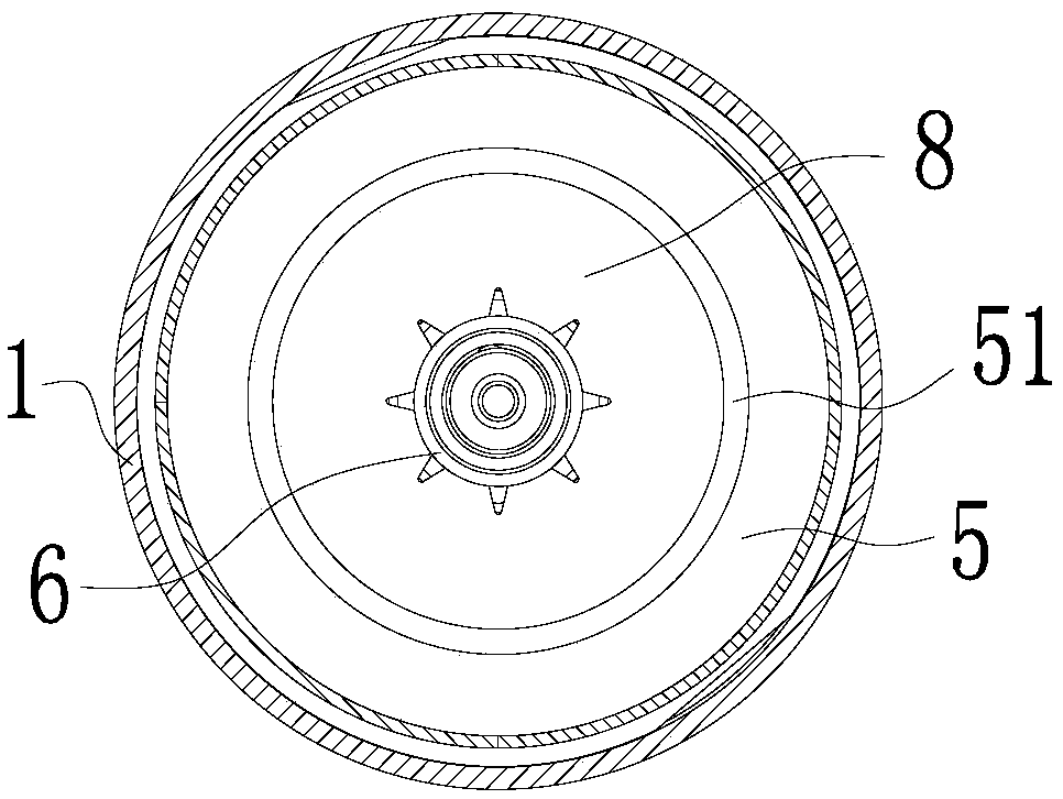
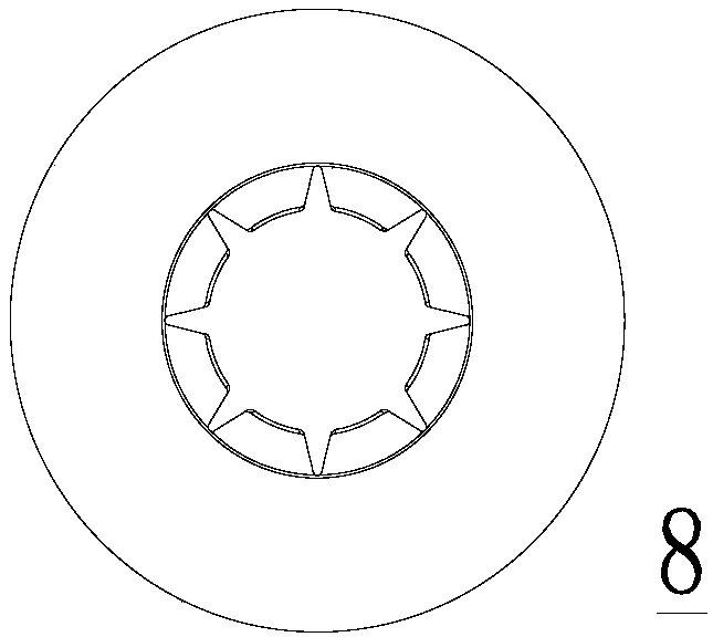
The invention relates to technical field of compressors, and discloses a horizontal compressor. The horizontal compressor comprises a shell body (1), a compressing mechanism (3), a motor (2) and a gasguiding device (5). The compressing mechanism is arranged in the shell body and comprises a main bearing (6). The motor drives the compressing mechanism to work and is provided with an insulating terminal board (4). The gas guiding device comprises a motor connection terminal and a compressing mechanism connection terminal. The motor connection terminal is connected with the insulating terminal board in a sealed way. The compressing mechanism connection terminal is in abut joint with the main bearing, and forms a terminal face seal with the main bearing. An airflow channel is formed between the compressing mechanism and the motor. The airflow channel passes through an inner cavity of the gas guiding device. The design of the horizontal compressor effectively improves the air tightness between the gas guiding device and the compressing mechanism. Thus, a refrigerant is prevented from flowing out from the gap between the gas guiding device and the compressing mechanism. The horizontal compressor can improve the cooling effect of the motor and the oil-gas separating effect of the refrigerant, thereby improving energy efficiency and reliability of the horizontal compressor.

Description

technical field [0001] The invention belongs to the technical field of compressors, and in particular relates to a horizontal compressor. Background technique [0002] Compressors (such as horizontal compressors) are widely used. In order to reduce the oil output of the compressor, a gas guide device is usually added between the compression mechanism and the motor, so that a passing air gap is formed between the compression mechanism and the motor. The gas flow channel of the inner cavity of the gas guiding mechanism. [0003] But at present, due to the limited assembly process, there is often an assembly gap between the gas guiding device and the compression mechanism, so that most of the refrigerant discharged from the compression mechanism no longer flows through the motor, but directly flows away from the assembly gap. In this way, Not only will the cooling effect of the motor be reduced, but the refrigerant will not be able to fully separate oil and gas, thereby greatl...

Claims


Application Information

Patent Timeline
Patent Type & Authority Applications(China)
IPC IPC(8): F04C27/00F04C29/02F04C29/04F04C29/00
CPCF04C27/001F04C29/00F04C29/026F04C29/042
Inventor 郝唯
Owner GUANGDONG WELLING AUTO PARTS CO LTD
Why Eureka
Try Eureka