an oil-gas separator

An oil and gas separator, oil and gas technology, used in machines/engines, engine components, mechanical equipment, etc., can solve problems such as reducing oil and gas separation efficiency, and achieve the effect of improving oil and gas separation efficiency, reducing pressure, and good oil and gas separation effect.

Active Publication Date: 2016-08-31
CHONGQING CHANGAN AUTOMOBILE CO LTD
View PDF6 Cites 0 Cited by
  • Summary
  • Abstract
  • Description
  • Claims
  • Application Information

AI Technical Summary

Problems solved by technology

[0003] 1) When the engine is under low load or low torque, the air at the second outlet pipe will also enter the intake manifold along with the air passage in the oil-air separator, thus affecting the oil and gas from the crankcase to enter the oil-air separation through the oil-air pipe device, reducing the oil-gas separation efficiency;

Method used


Image

  • an oil-gas separator
  • an oil-gas separator
  • an oil-gas separator

Examples


Embodiment Construction

[0017] Below in conjunction with accompanying drawing and embodiment the present invention will be further elaborated:

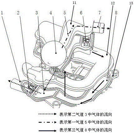
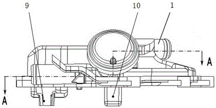
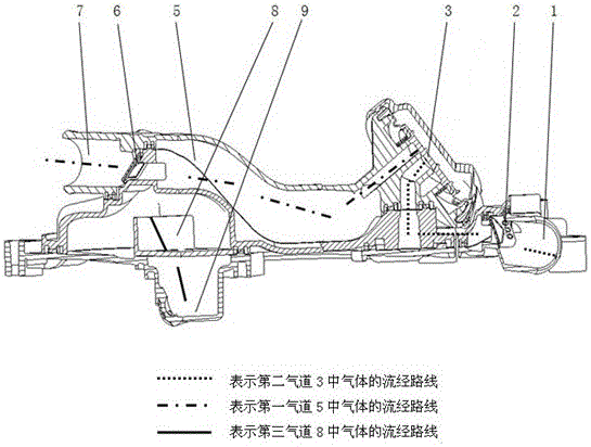
[0018] see Figure 1 to Figure 3 The oil-gas separator shown includes an oil-gas separator body, and the oil-gas separator body includes an upper cover 11 at the top, a lower cover 13 at the bottom, and a middle cover 12 between the upper and lower covers 11 and 13 , the upper cover 11, the middle cover 12 and the lower cover 13 are fixed together;

[0019] The body of the oil-gas separator is respectively provided with a first air outlet pipe 1 communicated with the intake manifold, a second air outlet pipe 7 communicated with the air inlet of the supercharger, an oil-air pipe 9 communicated with the crankcase and an oil return port 10 , the first air outlet pipe 1, the second air outlet pipe 7 and the oil-gas pipe 9 are all in communication with the oil-gas separation channel in the oil-gas separator body;

[0020] The oil-gas separation passage includes...


PUM


Abstract

The invention relates to an oil-gas separator. The oil-gas separator comprises an oil-gas separator body. A first gas discharging tube communicated with a gas feeding manifold, a second gas discharging tube communicated with the front of a supercharger and an oil-gas tube and an oil return port which are communicated with a crank case are arranged on the oil-gas separator body respectively. The first gas discharging tube, the second gas discharging tube and the oil-gas tube are communicated with an oil-gas separation channel in the oil-gas separator body. A first check valve is arranged in the first gas discharging tube, a second check valve is arranged in the second gas discharging tube, and a pressure control valve communicated with the oil-gas separation channel is arranged at the top of the oil-gas separator body. By means of the oil-gas separator, the gas flow in the gas channel can be effectively controlled, the oil-gas separation efficiency is improved, and the crank case pressure is reduced.

Description

technical field [0001] The invention relates to a ventilating system for a crankcase of an automobile supercharged engine, in particular to an oil-gas separator. Background technique [0002] The function of the oil-gas separator is to separate tiny oil droplets and gas through its own structure, and the separated small oil droplets return to the crankcase and finally return to the oil pan. The currently used oil-gas separator includes an upper cover, a middle cover and a lower cover. The first air outlet pipe communicated with the intake manifold, the second air outlet pipe communicated with the supercharger, and the crankshaft are arranged on the oil-air separator body. After the oil and gas enter the oil and gas separator through the oil and gas pipe, when the engine is at low load or low torque, that is, when the supercharger is not required to work (not supercharged), the first outlet pipe The negative pressure value is greater than the negative pressure value at the s...

Claims


Application Information

Patent Timeline
Patent Type & Authority Patents(China)
IPC IPC(8): F01M13/04
Inventor 李想李春乔艳军彭凤川王垣钦
Owner CHONGQING CHANGAN AUTOMOBILE CO LTD
Why Eureka
Try Eureka