[0011] Another object of the invention is to construct the electrode modules of CDI in a simple and effective
assembly. All modules should allow free path to liquids as in regular FTCs. In order to attain high adsorption efficiency, all of the impure liquid must be subjected to the static
electric field built within the electrode modules. This means that the fluid must pass between the charged electrodes and there is no bypath for the un-treated liquid to escape, as well as no concealment in the container of FTC for the liquid to remain un-treated. Thus, simple assemblies as normally used for capacitors, for example, spiral winding and parallel stacking, are adopted to make FTCs to fit into the housings of desirable shapes and dimensions in a liquid-treating
system. To fit the shapes of various housings, the electrode module can be in the form of cylinder, cube, or rectangle. Hermetic sealing and flow guides are provided in the treating units comprised of FTCs and housings to ensure the requisite pattern of liquid flow.
[0014] Still another object of the invention is to devise a
fully automatic CDI setup as a pre-treatment for the more expensive and fragile liquid-treating equipment such as ion-exchange and RO. CDI is capable of directly purifying high-concentration liquids such as
seawater, so the TDS of liquids can be reduced to the suitable levels for
ion exchange and RO that the service life of the latter can be prolonged. Because of the low cost of materials used, energy-efficiency of operation and
pollution-free characteristics, the
fully automatic CDI
system of the invention can offer
cross cutting benefits to the waste reduction of various liquids.
[0015] A further object of the invention is to devise a fully automatic CDI setup to recycle useful resources for reuse. During the regeneration of CDI electrode modules, a rinsing liquid is employed to transfer the desorbed ions, the ionic contaminants that are removed from the liquids at deionization, to a designated reservoir wherein useful resources can be concentrated and recovered. Not only the
sludge from the purification treatment is easy for disposal, the present invention also provides values added to the reduction of liquid wastes by recycling useful resources for reuse in an economical fashion.
[0024] It is known to people skilled in the art that the conducting plate employed in CDI is called substrate or
current collector, while the adsorbent is active material. The substrate can be in the form of foil, plate, mesh, or web. Deionization or desalt is the principal goal of CDI, the technique only requires a low
DC voltage, for example, 0.5-3V, so that
electrolysis is inhibited. Furthermore, both current collectors and active material should be adsorptive, conductive, and
inert in various harsh environments. If CDI is employed for
desalination,
titanium (Ti) is the best choice for the
current collector in terms of resistance to salt
corrosion and material cost. Nevertheless,
platinum (Pt) and
palladium (Pd) can be used as the substrate for the stringent applications such as
hemodialysis. Because of their absorption capability, large specific surface area, and low cost, activated carbons (ACs) are the most convenient choice for the active material of CDI. There are numerous ACs available on the market that makes the selection of material laborious. In addition to cost, the chosen AC should have minimum surface area of 1000 m.sup.2 / g, minimum size of 200 mesh, and 0% ash content. Other costly carbonaceous materials such as the Bucky ball, C.sub.60 and
carbon nanotube can also be used at low loading. For mild and neutral liquids,
metal oxides such as
manganese oxide (MnO.sub.2) and
magnetite (Fe.sub.3O.sub.4) having
specific adsorption so that the use of them is beneficial to special CDI applications. As the charging rate of capacitors is fast, CDI operations ought to be short for the surface of electrodes is quickly saturated with ion coverage. Under low
operating voltage and short
operating time, CDI is highly energy-efficient on reducing the TDS of liquids. It is estimated that CDI requires the consumption of energy no more than 1 KW / hr to desalinize 1 tonne (263 gallons) of 35,000 ppm
seawater to 250 ppm
fresh water.
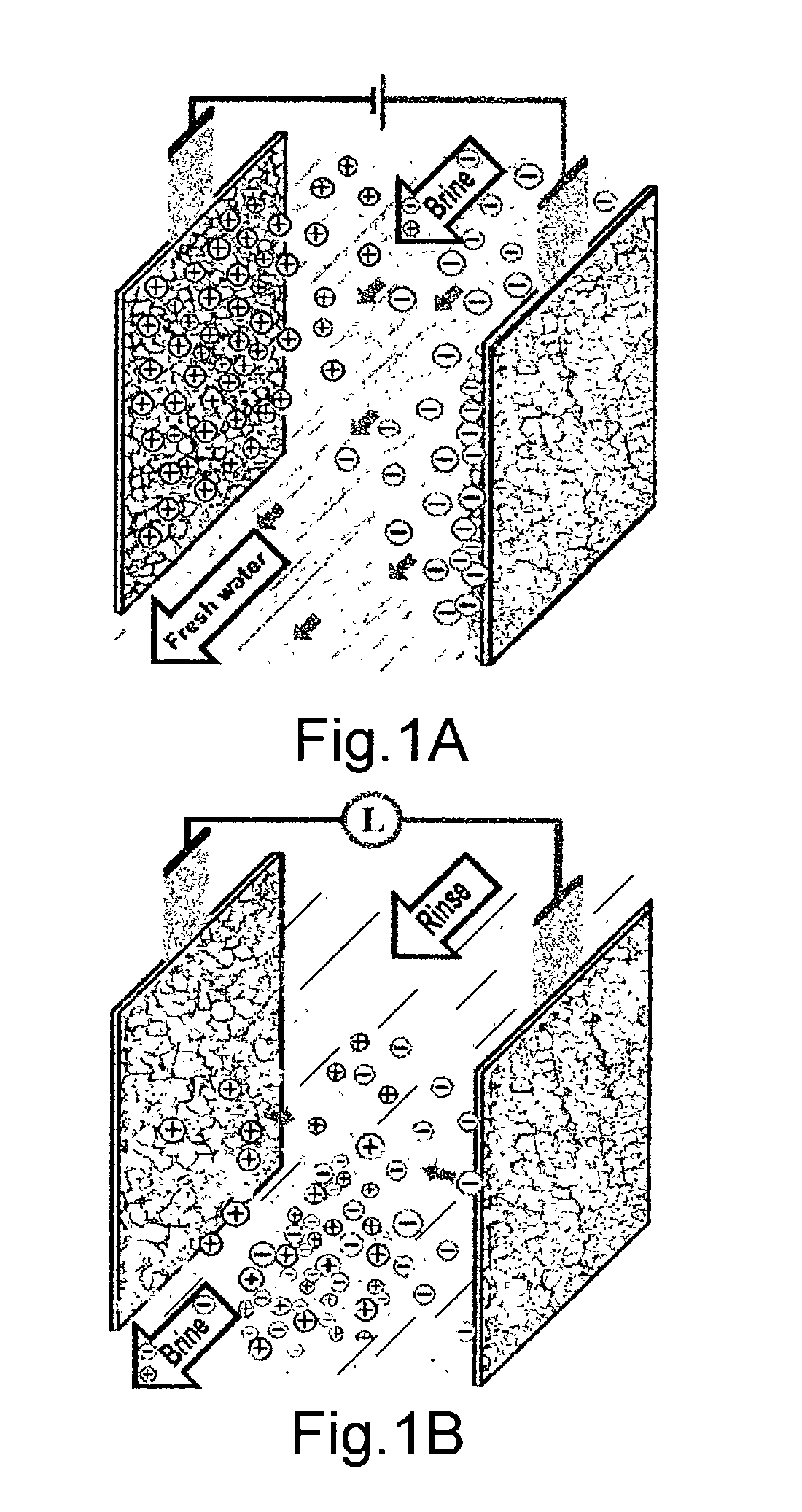
After treatment, the degree of purity of the
fresh water in FIG. 1A is determined by the adsorption capability, and the
effective surface area of the active material, as well as by the gap between the CDI electrodes.
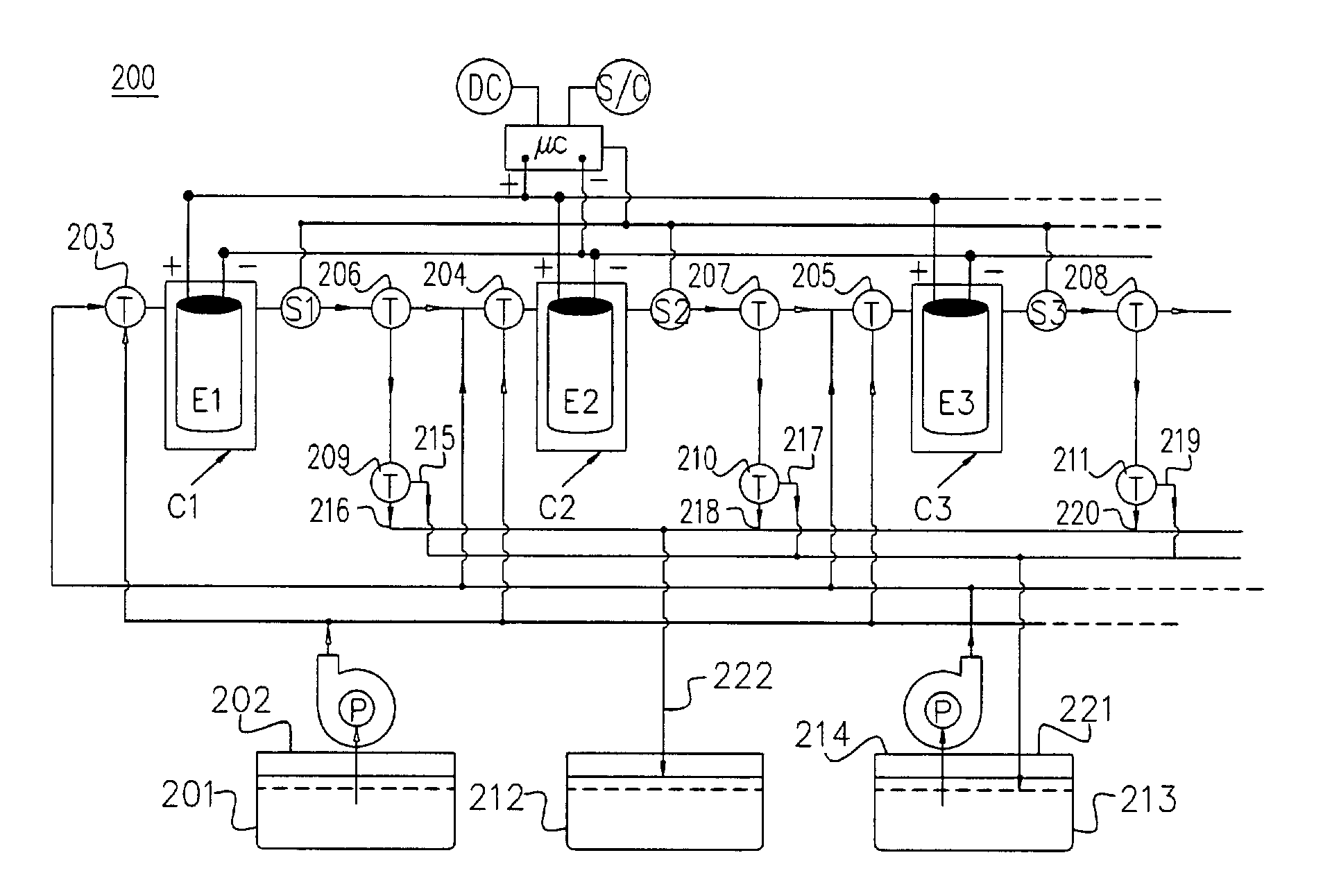
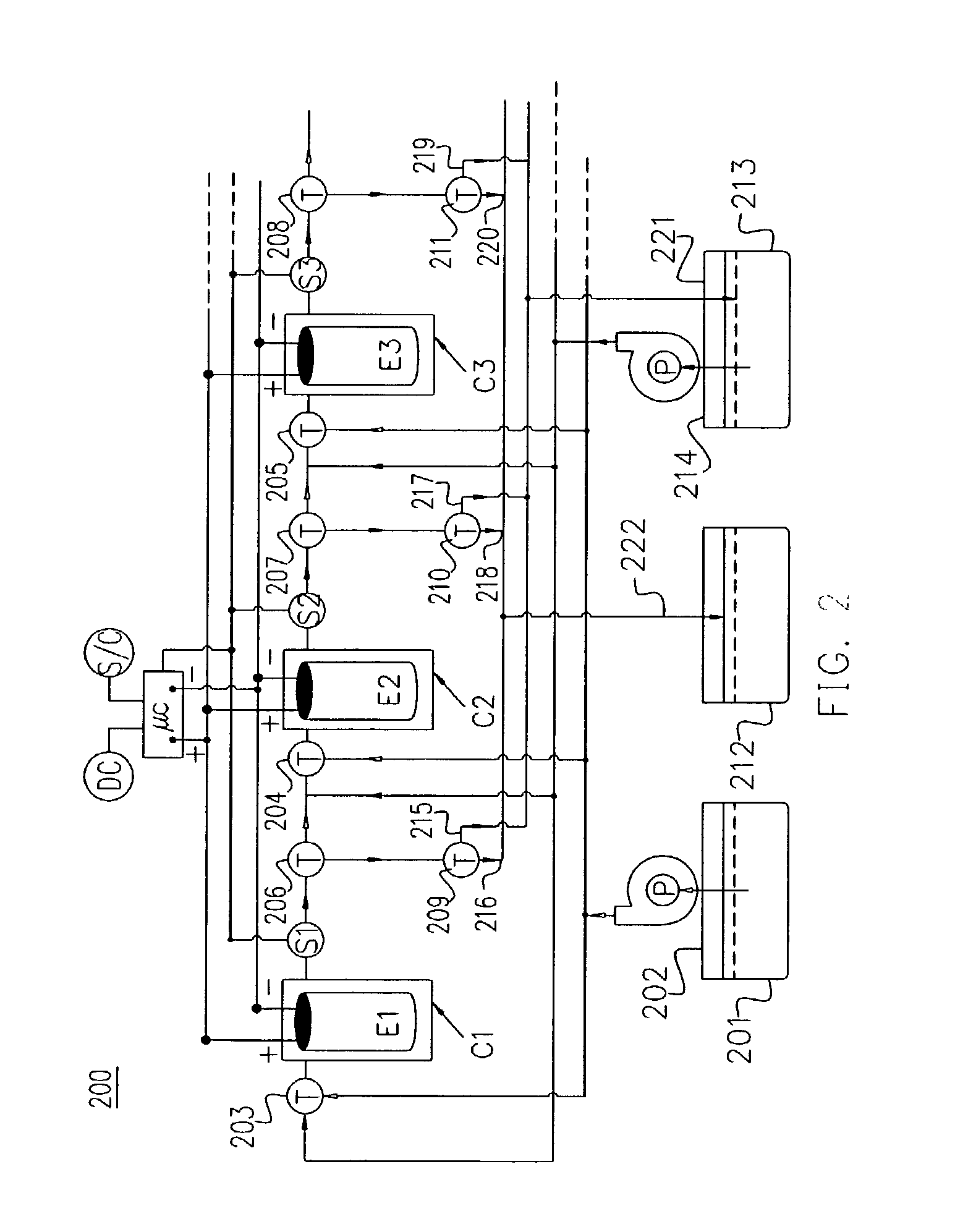
[0028] In the operation of automatic CDI 200, an impure liquid such as
seawater can be conveyed by pump 202 from tank 201 through electromagnetic fluid valve 203, 204 or 205 to the CDI treating unit C1, C2, or C3, respectively. As the impure liquid flows into the treating units, the micro-controller .mu. C will synchronously direct the DC power source to supply
electricity to the electrode module of that treating unit to perform deionization for a preset duration. The DC power source applies a
DC voltage to the treating unit for a period from 30 seconds to 4 minutes for deionization. On the conclusion of a deionization session, the on-line sensors S1, S2 and S3 measure the
conductivity, resistivity, pH, or
optical absorbance of the
effluent, in reference to a predetermined standard, to determine if the
effluent is ready for harvest, or it requires further deionization treatment. If the
effluent is pure according to the judgment, the sensor notifies the
microprocessor .mu. C to divert the
electromagnetic flow valve 206, 207 or 208 to allow the pure liquid flowing through
electromagnetic valve 209, 210 or 211, as well as through liquid
pipe line 216, 218, or 220, respectively, to line 222 and into tank 212 to store for later use, or for transporting to a local water-supply system. There is a check value arranged on line 222 (not shown in FIG. 2) to prevent pure liquid back flow from the
storage tank 212 back to the CDI treating unit (C1, C2, or C3). As long as the effluent is pure, more impure liquid can be conducted into that CDI treating unit (C1, C2, or C3) for deionization, otherwise, the influent will be switched from impure liquid (of tank 201) to the rinse supplied from tank 213 by the pumping of a pump 214. When the rinsing liquid flows to a CDI treating unit, the impure liquid flow to that unit will be terminated and all of the electromagnetic valves will be arranged, on the commands issued by the micro-controller .mu. C, for the pass of rinsing liquid. Same as deionization, regeneration of the CDI electrode modules in the presence of rinsing liquid is also conducted for a pre-set duration, such as a duration less than one minute. On the conclusion of a regeneration session, the effluent of rinsing liquid, together with the desorbed ions, flows through
pipe line 215, 217 or 219 into line 221 and back to the tank 213 wherefrom valuable ions can be concentrated and recycled for reuse, or collected as by-products for sale enhancing the value of CDI treatment.
[0029] Deionization of liquid and regeneration of the CDI electrode modules should be conducted simultaneously on separate groups of CDI treating units for two reasons. The first reason is that impure liquids in the
industrial scale are frequently copious, the impure liquids should continuously flow through many parallel sets of CDI treating groups, each group containing a number of CDI treating units connected in series, to attain a high
throughput. The second reason is that a tandem CDI treating units can facilitate the
energy recovery at regenerating the electrode modules. More units connected in series, higher
recovery rate and deeper
discharge of each electrode modules can be attained. As the
discharge of capacitors will cease when an equal potential is arrived, the serially connected capacitors can provide a larger potential range for discharge, thus a deeper discharge on each
capacitor. While some groups of CDI units are subjected to regeneration, other groups will be performing deionization. Deionization and regeneration are quickly repeated and interchangeably among many groups of tandem CDI treating units. Therefore,
fresh water and
electricity are co-generated in the automatic CDI system of the present invention. In order to cope with the fluid flow rate, which is considerably slower than the electronic response, deionization and regeneration of CDI are accordingly set to appropriate durations of operation. The flow pattern through the whole CDI treating system can be programmed for any liquid flowing in any group of CDI treating units for any duration, arranged in any desired sequence of events.

