Cyclone-type dust-collecting apparatus for vacuum cleaner

a vacuum cleaner and dust collection technology, which is applied in the field of vacuum cleaners, can solve the problems of affecting the suction force may overload the motor the vacuum cleaner is difficult to maintain, so as to improve the overall cleaning efficiency of the vacuum cleaner, improve the stability and directionality of the air vortex, and facilitate maintenance and care.

Inactive Publication Date: 2005-11-29
SAMSUNG GWANGJU ELECTRONICS CO LTD
View PDF23 Cites 118 Cited by
  • Summary
  • Abstract
  • Description
  • Claims
  • Application Information

AI Technical Summary

Benefits of technology

[0015]It is an object of the present invention to provide a cyclone-type dust-collecting apparatus having a structure that enables a user to more easily maintain and care for the vacuum cleaner, in particular by providing a grill assembly that can easily be separated from the rest of the structure for removal of the collected dust and dirt, for example, by washing. It is another object of the present invention to provide a cyclone-type dust-collecting apparatus for a vacuum cleaner that, improves the stability and the directionality of the air vortex formed in a cyclone body of the apparatus of and thereby improving the overall cleaning efficiency of the vacuum cleaner.
[0023]The cyclone body also has a guide member disposed at a sidewall of the air inflow port of the cyclone body and has a guide surface of a predetermined curvature for guiding movement of the air drawn into the air inflow port to increase stableness and directionality of the air vortex. Accordingly, the cleaning efficiency is improved and reverse flow of the dirt is prevented due to increased stability and directionality of the air vortex. The radius of curvature of the guide surface is smaller than the radius of a portion in the cyclone body in which the air vortex is maintained.

Problems solved by technology

The conventional cyclone-type dust-collecting apparatus for a vacuum cleaner as described above, however, is difficult to maintain, mainly due to the difficulty associated with the removal of the dust gathered in and around the fine passage holes 42 of the grill assembly 40.
When the fine passage holes 42 are clogged with the dirt and dust, deterioration of the suction force may overload the motor of the vacuum cleaner.
However, removing the accumulated dust and dirt may not be an easy task to a user due to the way the grill assembly 40 is connected to the cyclone body 20 in a conventional cyclone-type dust-collecting apparatus.
Therefore, inevitably a sanitary problem results.

Method used


Image

  • Cyclone-type dust-collecting apparatus for vacuum cleaner
  • Cyclone-type dust-collecting apparatus for vacuum cleaner
  • Cyclone-type dust-collecting apparatus for vacuum cleaner

Examples


Embodiment Construction

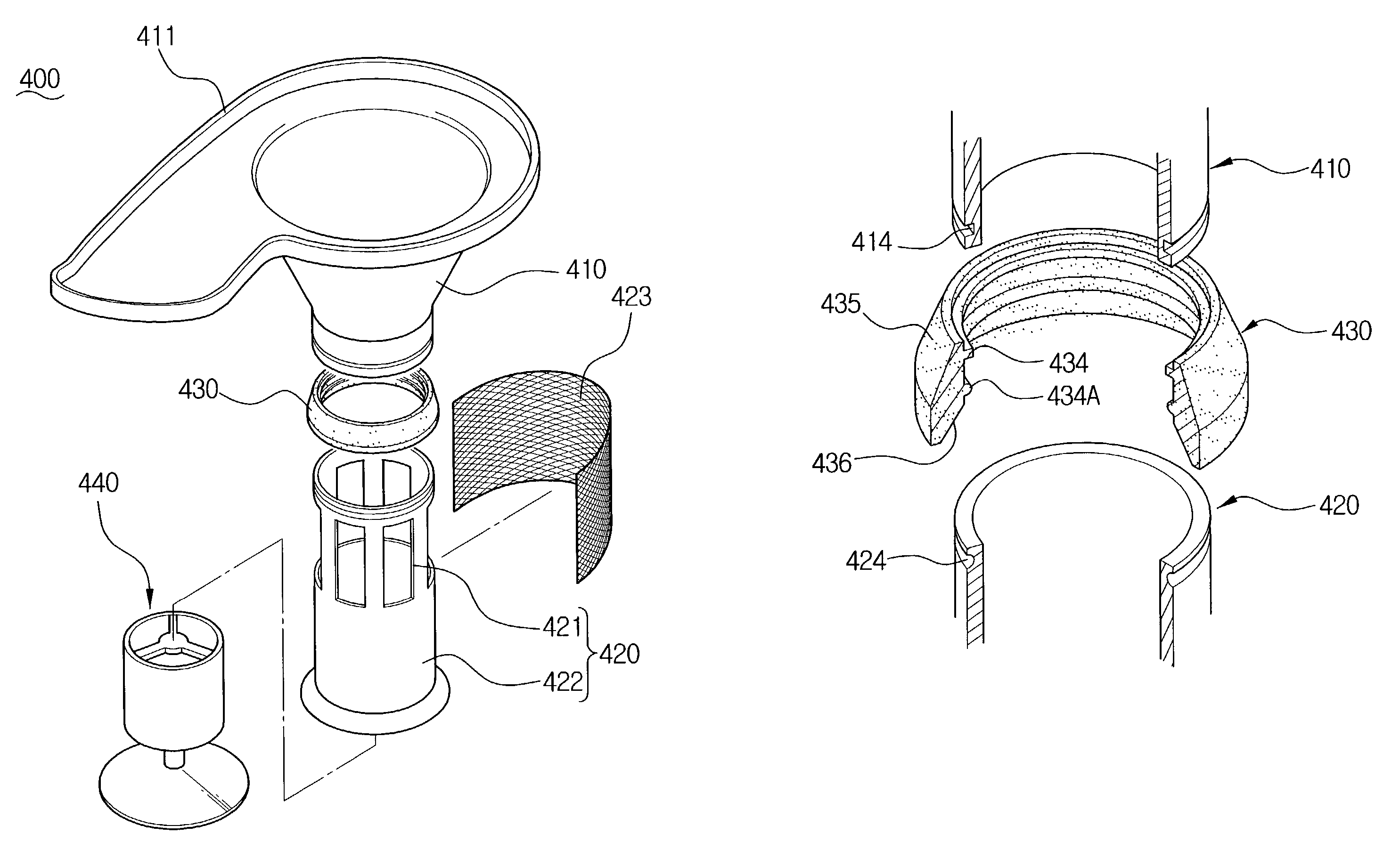
[0035]Now referring to FIGS. 4–9, a cyclone-type dust-collecting apparatus for a vacuum cleaner according to an embodiment of the present invention comprises a cyclone body 20, a dust-collecting receptacle 30, and a grill assembly 400.

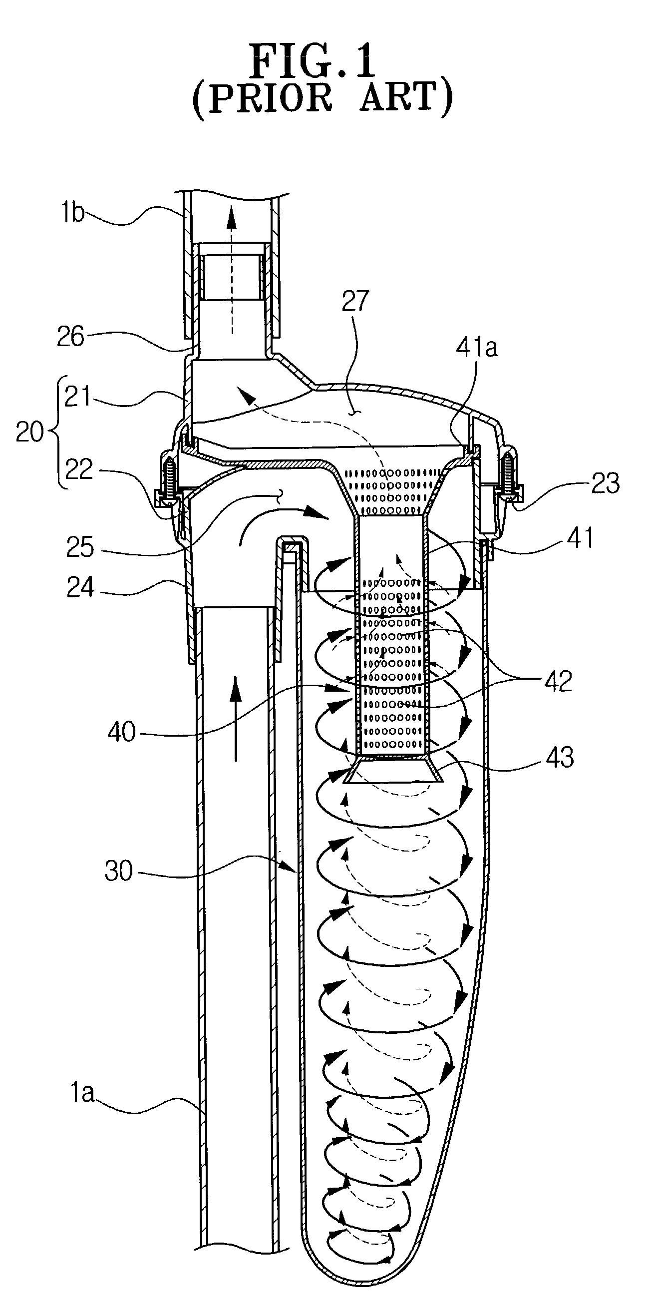
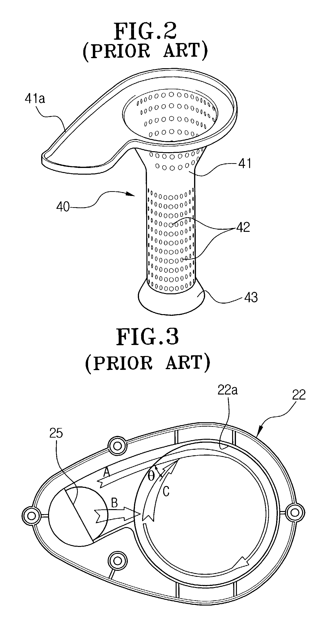
[0036]The cyclone body 20 includes an upper body 21 and a lower body 22 that are fastened together by a plurality of screws 23. The lower body 22 is provided with a first connection pipe 24 connected to an extension pipe 1a extending toward a suction port of a cleaner (not shown) and an air inflow port 25 being in fluid communication with the first connection pipe 24. The upper body 21 includes a second connection pipe 26 connected to one end of a second extension pipe 1b, and the other end of the extension pipe 1b is connected to a body (not shown) of the vacuum cleaner. The second connection pipe 26 is also connected to an air outflow port 27 (FIG. 9) in fluid communication with the second connection pipe 26. On the sidewall 22b (FIG. 5) of the air i...


PUM

PropertyMeasurementUnit
flexibleaaaaaaaaaa
diameteraaaaaaaaaa
stabilityaaaaaaaaaa

Abstract

A cyclone-type dust-collecting apparatus for a vacuum cleaner comprises a conically shaped grill assembly disposed at the air outflow port of a cyclone body. The grill assembly includes a grill portion and prevents reverse flow of dust and dirt from the cyclone body. The grill assembly members are easily separable to allow a user to easily remove the dirt collected in the grill portion by simply separating the second grill member from the connection member and washing the second grill member with water.

Description

BACKGROUND OF THE INVENTION[0001]1. Field of the Invention[0002]This application relates generally to a vacuum cleaner and, more particularly, to a cyclone-type dust-collecting apparatus for a vacuum cleaner that generates an air vortex of dust-laden air drawn into the cyclone-type dust-collecting apparatus and utilizes the centrifugal force of the air vortex to separate the dust and dirt in the dust-laden air.[0003]2. Description of the Prior Art[0004]FIGS. 1–3 schematically illustrate the structure of a conventional cyclone-type dust-collecting apparatus for a vacuum cleaner as disclosed in U.S. Pat. No. 6,195,835 (assigned to the same assignee as the present application).[0005]Now referring to FIG. 1, the conventional cyclone-type dust-collecting apparatus for a vacuum cleaner is generally made up of a cyclone body 20, a dust-collecting receptacle 30, and a grill assembly 40.[0006]The cyclone body 20 is divided into an upper body 21 and a lower body 22 that are secured by a plura...

Claims


Application Information

Patent Timeline
Patent Type & Authority Patents(United States)
IPC IPC(8): A47L9/10A47L9/16B01D45/14B04C5/13
CPCA47L9/104A47L9/1666A47L9/1691B01D45/14B04C5/13Y10S55/03A47L9/102A47L9/1683A47L9/16
Inventor OH, JANG-KEUNLEE, HYUN-JUJIN, HYOUNG-JONG
Owner SAMSUNG GWANGJU ELECTRONICS CO LTD
Why Eureka
Try Eureka