
Motor reducer module

A technology of reducer and motor, applied in the direction of electromechanical devices, control mechanical energy, electric components, etc., can solve the problems of the overall configuration space and the difficulty of effectively reducing the volume, and achieve the effect of reducing the configuration space

Inactive Publication Date: 2020-06-02
SAFEWAY ELECTRO MECHANICAL CO LTD +1
View PDF11 Cites 0 Cited by
  • Summary
  • Abstract
  • Description
  • Claims
  • Application Information

AI Technical Summary

Problems solved by technology

[0006] In view of this, the purpose of the present invention is to provide a modular design of the motor reducer to improve the overall configuration space of the traditional motor reducer and the problem that the volume is difficult to effectively reduce, especially to abandon the use of the inner gear ring to improve overall system efficiency and reduced noise

Method used


Image

  • Motor reducer module
  • Motor reducer module
  • Motor reducer module

Examples


Embodiment Construction

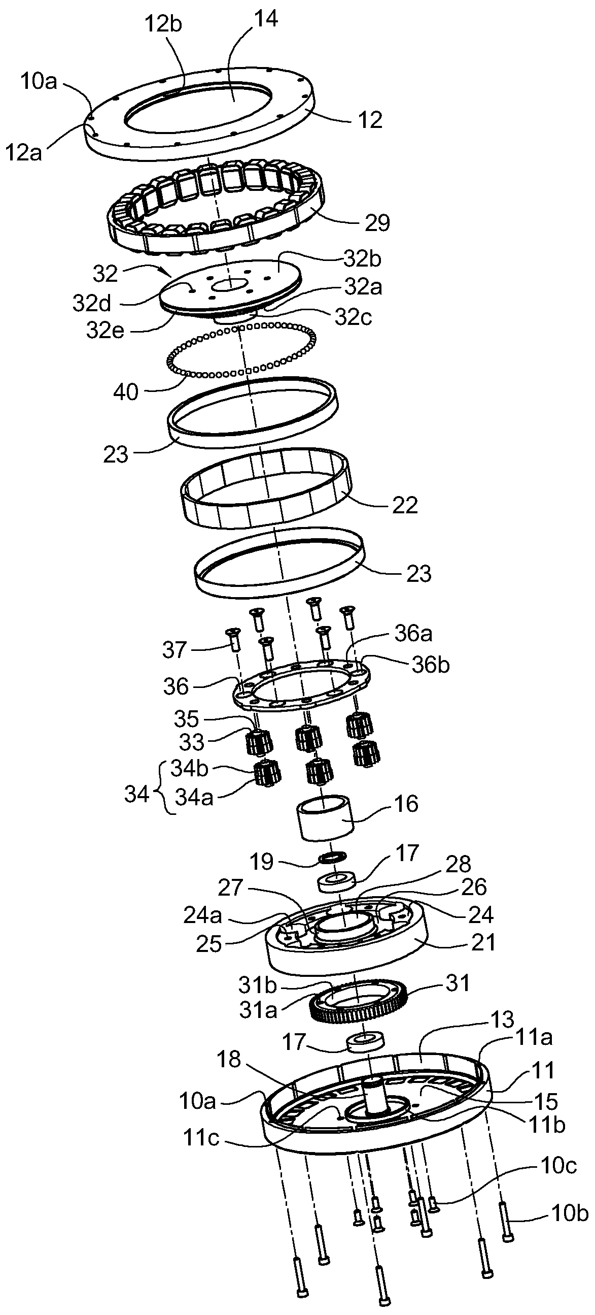
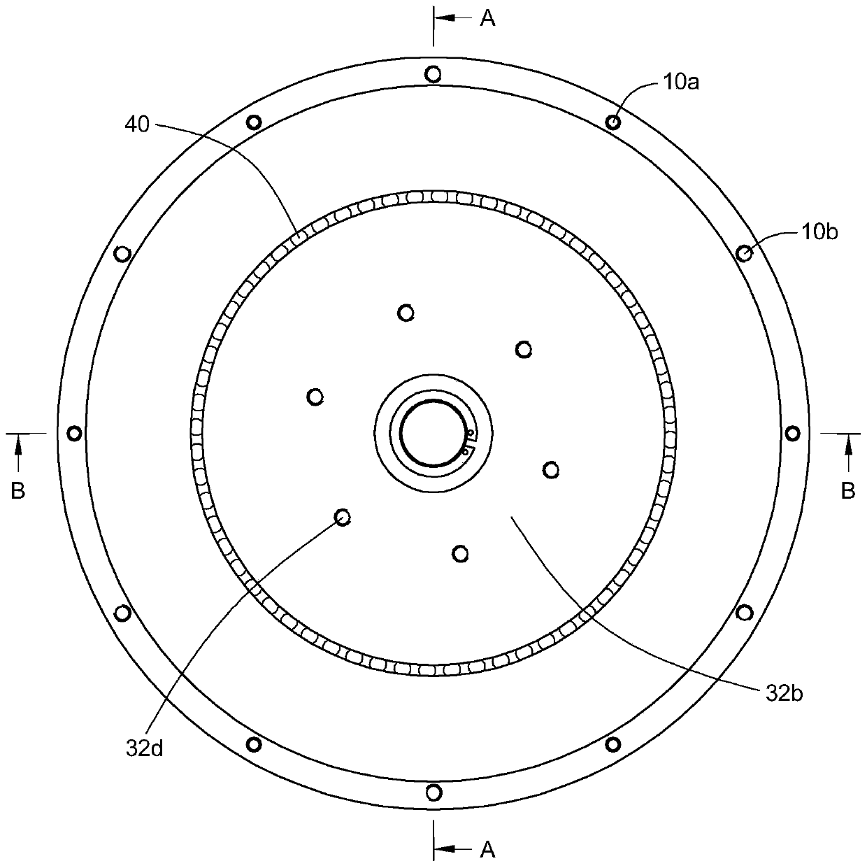
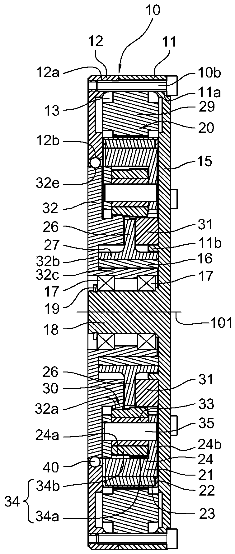
[0029] First, please incorporate the Figure 1 to Figure 6 , discloses the configuration details of a preferred embodiment of the present invention, and illustrates the structural composition of the motor reducer module provided by the present invention, including: a casing 10, a reducer composed of a planetary gear train 30 and a Hollow type motor 20. The casing 10 is used as the fixed end of the whole module and is used to accommodate the planetary gear train 30 of the motor 20 and the speed reducer. The inside of the casing 10 provides a centerline 101 for disposing a central shaft 18 and making the central shaft 18 is fixed in the casing 10 ; wherein, the motor 20 surrounds the periphery of the planetary gear train 30 of the speed reducer and is located in the casing 10 .

[0030] Depend on figure 1 and image 3It can be seen that the casing 10 includes a first shell 11 and a second shell 12 . The first shell 11 is formed with a plurality of through holes 11a, and the ...


PUM


Abstract

The invention provides a motor speed reducer module. The motor speed reducer module is characterized in that a hollow motor and a planetary gear train are configured inside a machine shell, a permanent magnet train of a motor is stuck to a planetary gear bearing base of the planetary gear train to form an annular rotor, and the planetary gear comprises at least one planetary gear set synchronouslyrotating around the motor rotor and a fixed sun gear and a movable sun gear which are formed on the two sides of the annular rotor; when the annular rotor rotates, the planetary gear set is driven torotate, the planetary gear set is guided by the fixed sun gear to rotate automatically, then, the movable sun gear is driven to perform speed reduction output, and the problem that a traditional motor speed reducer can only output a limited reduction ratio and the whole configuration space and size are difficultly and effectively decreased is solved.

Description

technical field [0001] The invention relates to a modular design combining a motor and a gear reduction mechanism, in particular to a motor reducer module with a flat appearance. Background technique [0002] A gear motor is an integrated power drive device that combines an electric motor and a gear reduction mechanism or a non-gear reducer. Generally, under the same driving voltage, if a motor has low-speed and high-torque output, the volume is usually relatively large, and the production cost is also high. If it is high-speed and low-torque output, the volume is usually relatively small, and the production The cost is also low, and the motor reducer allows the motor to generate high speed and low torque through the reducer to convert it into low speed and high torque, providing huge torque output in a relatively small volume. [0003] The application of traditional motor reducers can be seen in patent documents such as U.S. Patent No. 6196347, No. 6296072, and No. 6629574...

Claims


Application Information

Patent Timeline
Patent Type & Authority Patents(China)
IPC IPC(8): B60K17/08H02K7/116
CPCB60K17/08H02K7/116
Inventor 梁嘉生
Owner SAFEWAY ELECTRO MECHANICAL CO LTD
Learn More