
An automatic continuous stamping device for small hardware

A technology of small hardware parts and stamping devices, applied in the field of stamping devices, can solve the problems of low efficiency and danger, lack of feeding and conveying platforms, etc., and achieve the effect of avoiding danger and using safely

Active Publication Date: 2019-04-05
苏州圣亚精密机械有限公司
View PDF1 Cites 0 Cited by
  • Summary
  • Abstract
  • Description
  • Claims
  • Application Information

AI Technical Summary

Problems solved by technology

[0004] Aiming at the deficiencies in the prior art, the purpose of the present invention is to provide an automatic continuous stamping device for small hardware to solve the problem of the lack of a feeding and conveying platform in the traditional automatic continuous stamping device for small hardware in the prior art, and its discharge is often carried out manually. The problem of low efficiency and certain danger

Method used


Image

  • An automatic continuous stamping device for small hardware
  • An automatic continuous stamping device for small hardware

Examples


Embodiment Construction

[0018] In order to make the technical means, creative features, goals and effects achieved by the present invention easy to understand, the present invention will be further described below in conjunction with specific embodiments.

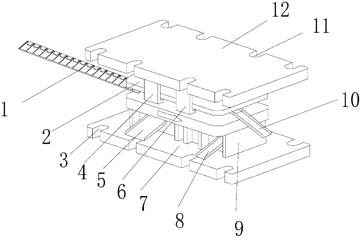
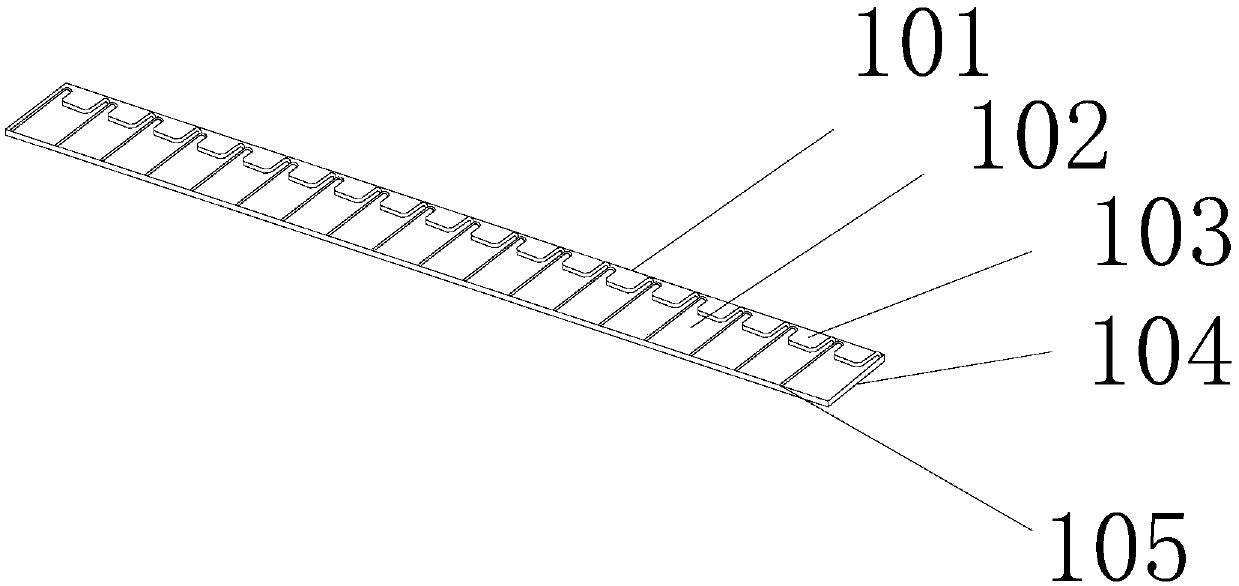
[0019] see figure 1 and figure 2 , the present invention provides a technical scheme of automatic continuous stamping device for small hardware parts: its structure includes: hardware fixing piece 1, mold upper plate 2, base fixing gap 3, left shock absorbing gasket 4, left waste material outlet 5, right side Damping gasket 6, base 7, waste material outlet 8 on the right side, mold support seat 9, hardware outlet 10, pressure plate fixing gap 11, pressure plate 12, and the middle part of the upper end of the base 7 is provided with a mold support seat 9, The left side waste material outlet 5, the right side waste material outlet 8 and the hardware outlet 10 are connected to the mold support seat 9. The bottom end of the pressure applying plate ...


PUM


Abstract

The invention discloses an automatic small hardware piece continuous punching device. The automatic small hardware piece continuous punching device structurally comprises a hardware fixing sheet, a die upper plate, base fixing notches, a left damping gasket, a left waste outlet, a right damping gasket, a base, a right waste outlet, a die supporting base, a hardware piece outlet, pressure application fixing notches and a pressure application plate. The die supporting base is arranged at the middle portion of the upper end of the base, and the left waste outlet, the right waste outlet and the hardware piece outlet are connected with the die supporting base. The die upper plate is arranged at the bottom end of the pressure application plate, and the left damping gasket and the right damping gasket are arranged on the left side and the right side of the die upper plate. The automatic small hardware piece continuous punching device is provided with the hardware fixing sheet, hardware piecescan be automatically and evenly conveyed into the device, manual conveying dangerousness is avoided, and using is safe.

Description

technical field [0001] The invention relates to an automatic continuous punching device for small hardware, belonging to the field of punching devices. Background technique [0002] At present, stamping hardware is mainly processed by continuous stamping equipment. The raw material for continuous stamping processing is usually a sheet-shaped strip. The existing continuous stamping equipment includes an upper mold and a lower mold. For the stripper plate and the lower template formed by stamping, during continuous stamping, the strip is placed between the stripper plate and the lower template for stamping. [0003] The prior art discloses a metal stamping die with an application number of 201621383744.7, which includes an upper die, a lower die, and a guide mechanism arranged between the upper die and the lower die; the upper die includes: an upper mounting plate, The upper mold connecting plate, the pushing plate and the first ball guide column guide sleeve; the lower mold ...

Claims


Application Information

Patent Timeline
Patent Type & Authority Patents(China)
IPC IPC(8): B21D43/04B21D43/00B21D37/10
CPCB21D37/10B21D43/003B21D43/04
Inventor 彭敏
Owner 苏州圣亚精密机械有限公司
Learn More