Eureka AIR delivers breakthrough ideas for toughest innovation challenges, trusted by R&D personnel around the world.

Feeding mechanism of yarn switcher

A thread device and yarn feeding technology, which is applied in the field of knitting machine thread changer, can solve problems such as high yarn feeding point and unstable yarn feeding, and achieve the effects of improving production efficiency, simple structure, and meeting the needs of yarn feeding

Active Publication Date: 2018-03-23
TANGSHAN WUGU ELECTROMECHANICAL EQUIP CO LTD
View PDF13 Cites 0 Cited by
  • Summary
  • Abstract
  • Description
  • Claims
  • Application Information

AI Technical Summary

Problems solved by technology

[0002] The function of the thread changer of the knitting machine is to meet the needs of a variety of colored yarns when weaving on the knitting machine. The working principle is that a certain colored yarn participates in weaving during production. The device controls the action of the clamping and cutting device, introduces the colored yarn that needs to be replaced into the knitting area, and presses the knitting needle into the knitting needle by the yarn pressing plate of the knitting machine itself to participate in knitting. On the yarn cutting device, waiting for the next weaving, the process of introducing the yarn into the knitting area and the yarn pressing plate of the knitting machine into the knitting needle is called yarn feeding. The yarn feeding structure of the traditional thread changer exists during use. High yarn feeding point, unstable yarn feeding and other shortcomings affect production

Method used


Image

  • Feeding mechanism of yarn switcher
  • Feeding mechanism of yarn switcher
  • Feeding mechanism of yarn switcher

Examples


Embodiment Construction

[0034] The present invention will be further described below in conjunction with the examples, the purpose is only to better understand the contents of the present invention, therefore, the examples given do not limit the protection scope of the present invention.

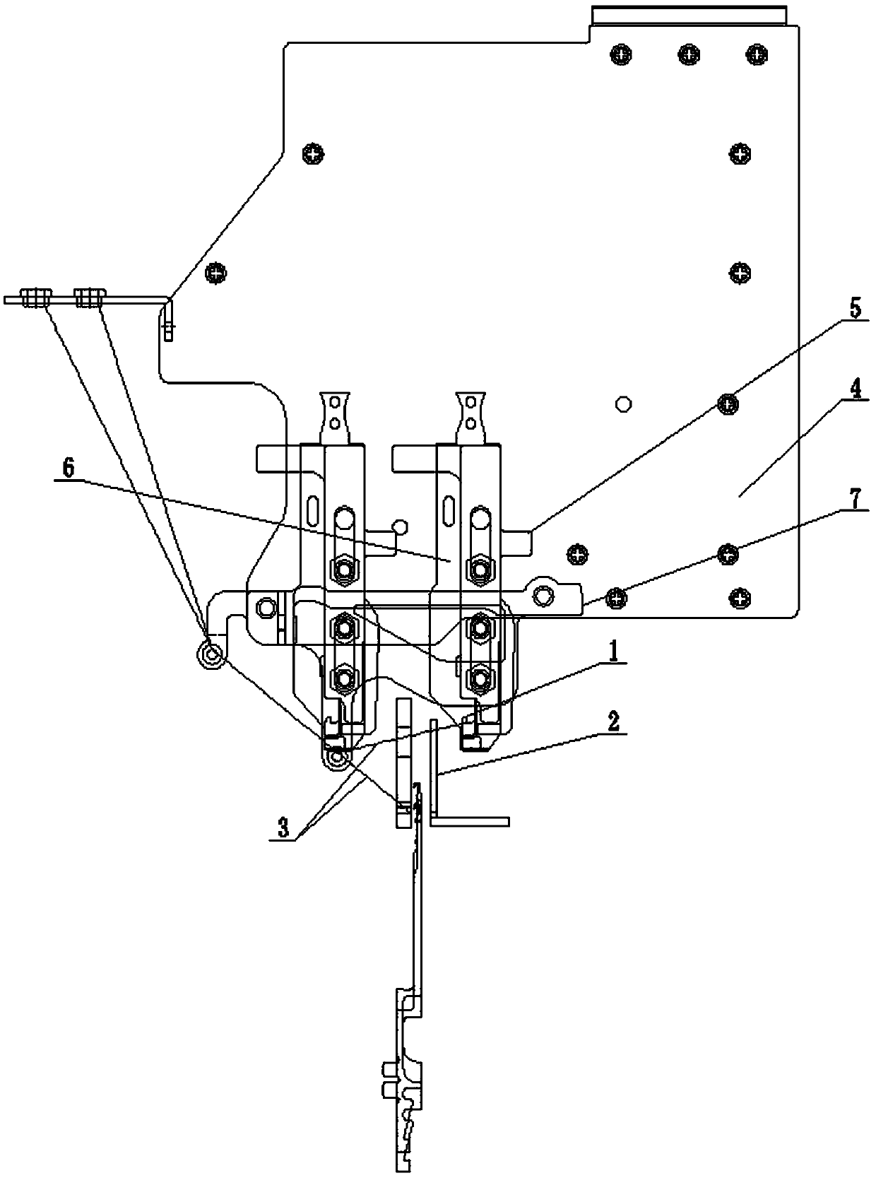
[0035] see figure 1 , in the prior art, the yarn clamping and cutting device 5 on the main body 4 of the yarn changer is controlled by the controller to move horizontally, and the yarn 3 to be replaced is introduced into the knitting area to form the first yarn feeding point 1, and is passed through the knitting machine. The first yarn pressing plate 2 is pressed into or introduced into the knitting needles to participate in weaving.

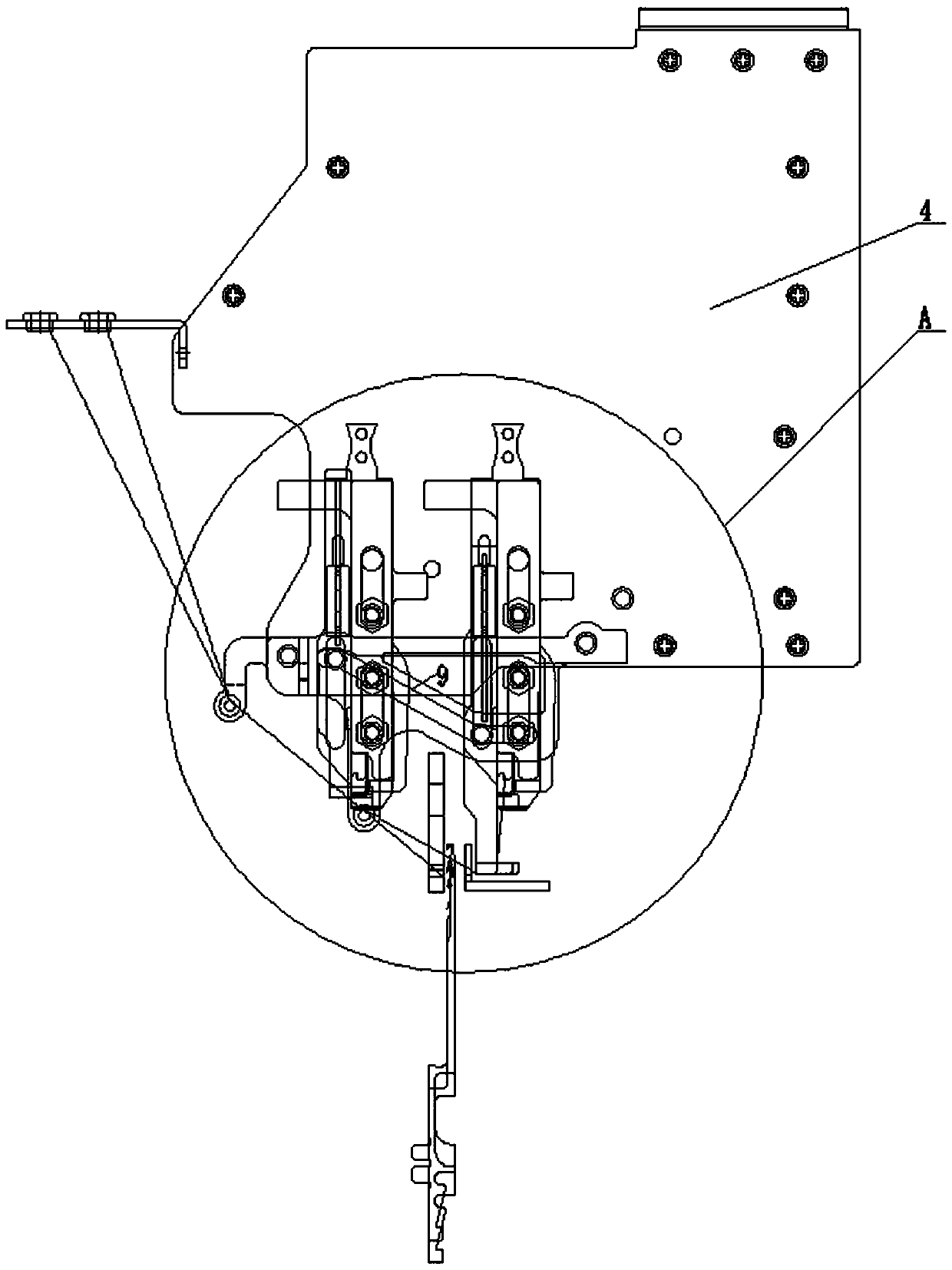
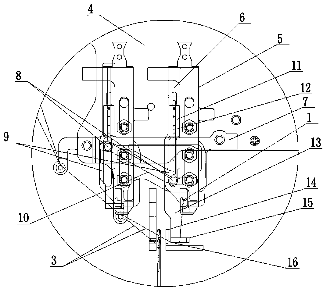
[0036] see figure 1 , figure 2 , image 3 , Figure 4 , Figure 5 , Figure 6 , Figure 7 , Figure 8 , Figure 9 , Figure 10 , Figure 11 , Figure 12 , Figure 13 , Figure 14 , Figure 15 , Figure 16 , Figure 17 , Figure 18 , Figure 19 , Figure 20 , Fi...


PUM


Abstract

The invention relates to a feeding mechanism of a yarn switcher. The feeding mechanism of the yarn switcher comprises a yarn clamping and shearing device, a separating plate, a sliding plate and a connecting plate, wherein the sliding plate is mounted on the main yarn shearing blade of the yarn clamping and shearing device and provided with a connecting plate vertical sliding long hole and a rivet, and the lower end of the sliding plate is provided with a yarn pressing head; the main yarn shearing blade is provided with a rivet vertical sliding long hole; the separating plate is provided witha rivet inclined sliding long hole; one end of the rivet, which is opposite to the main yarn shearing blade, extends into the rivet yield vertical sliding long hole, and the other end of the rivet extends into the rivet inclined sliding long hole; during linear movement, the main yarn shearing blade drives the rivet of the sliding plate through the connecting plate to slide inside the rivet yieldvertical sliding long hole or the rivet inclined sliding long hole, meanwhile, the rivet drives the sliding plate to slide downwards through the connecting plate vertical sliding long hole so that theyarn pressing head can press yarns. The feeding mechanism of the yarn switcher can lower the yarn feeding point during yarn switching and ensure stable yarn feeding of the yarn switcher, and meanwhile, is simple in structure and capable of improving the production efficiency.

Description

technical field [0001] The invention relates to a thread changer of a knitting machine, in particular to a yarn feeding structure of the thread changer. Background technique [0002] The function of the thread changer of the knitting machine is to meet the needs of a variety of colored yarns when weaving on the knitting machine. The working principle is that a certain colored yarn participates in weaving during production. The device controls the action of the clamping and cutting device, introduces the colored yarn that needs to be replaced into the knitting area, and presses the knitting needle into the knitting needle by the yarn pressing plate of the knitting machine itself to participate in knitting. On the yarn cutting device, waiting for the next weaving, the process of introducing the yarn into the knitting area and the yarn pressing plate of the knitting machine into the knitting needle is called yarn feeding. The yarn feeding structure of the traditional thread cha...

Claims


Application Information

Patent Timeline
Patent Type & Authority Applications(China)
IPC IPC(8): D04B15/60D04B27/10
CPCD04B15/60D04B27/10Y02W30/66
Inventor 张燚
Owner TANGSHAN WUGU ELECTROMECHANICAL EQUIP CO LTD
Why Eureka
Eureka Blog
Learn More