Same-layer type combined highway and railway bridge for same-direction travelling

A road-rail dual-purpose bridge, the same-layer technology, applied in bridges, bridge applications, noise absorption devices, etc., can solve the adverse effects of aerodynamic wind stability on passing cars, affect road and rail driving safety, and glare for car drivers, etc. problems, to reduce the probability of traffic accidents, avoid psychological impact and unfavorable glare, and reduce adverse effects

Pending Publication Date: 2018-04-13
CHINA RAILWAY ERYUAN ENG GRP CO LTD
View PDF0 Cites 0 Cited by
  • Summary
  • Abstract
  • Description
  • Claims
  • Application Information

AI Technical Summary

Problems solved by technology

[0004] The purpose of the present invention is to overcome existing in the prior art that road driving direction and railway driving direction are opposite in some countries, cause the relative speed of automobile and train when meeting on the same floor type road-rail dual-purpose bridge, extremely large, It causes a great psychological impact

Method used


Image

  • Same-layer type combined highway and railway bridge for same-direction travelling
  • Same-layer type combined highway and railway bridge for same-direction travelling
  • Same-layer type combined highway and railway bridge for same-direction travelling

Examples


Example Embodiment

[0029] Example 1

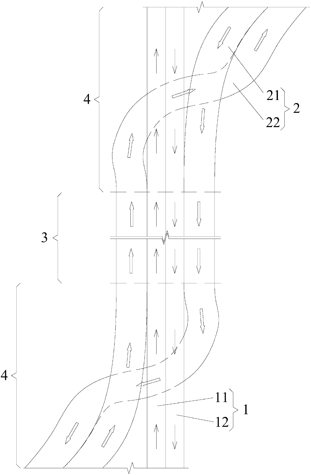
[0030] like image 3 As shown in the figure, a same-level road-rail dual-purpose bridge traveling in the same direction according to the present invention includes a parallel section 3 on the bridge and two lead sections 4 connected to both ends of the parallel section 3 on the bridge. .

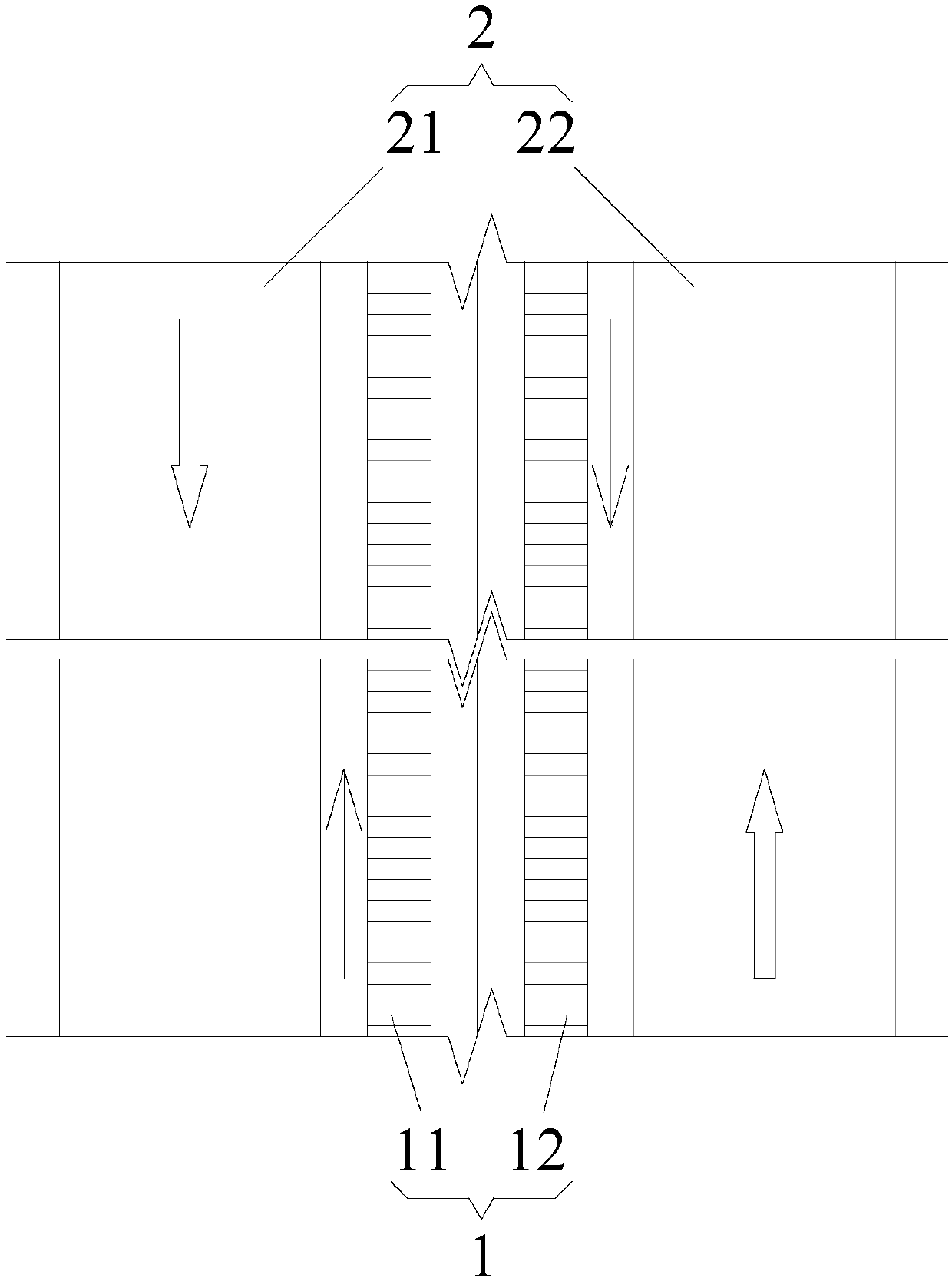
[0031] The highway-rail parallel section 3 on the bridge and the bridge deck of each of the lead sections 4 include a railway line 1 and a highway lane 2, the railway line 1 includes a left railway line 11 and a right railway line 12, and the highway lane 2 includes a left lane 21 and a right lane 22, the railway line 1 in the parallel section 3 on the bridge is located in the middle, the left lane 21 and the right lane 22 are located on both sides of the railway line 1, each The left lane 21 and the right lane 22 in the lead segment 4 cross and change lanes, and the left lane 21 or the right lane 22 in each lead segment 4 crosses the railway line 1, that is, the In the...

Example Embodiment

[0034] Example 2

[0035] like Figure 4 As shown in the figure, a same-level road-rail dual-purpose bridge traveling in the same direction according to the present invention includes a parallel section 3 on the bridge and two lead sections 4 connected to both ends of the parallel section 3 on the bridge. .

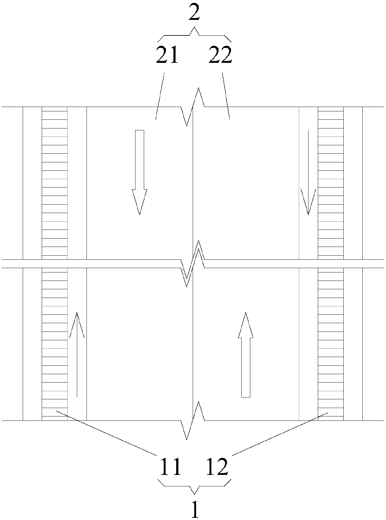
[0036]The highway-rail parallel section 3 on the bridge and the bridge deck of each of the lead sections 4 include a railway line 1 and a highway lane 2, the railway line 1 includes a left railway line 11 and a right railway line 12, and the highway lane 2 includes a left lane 21 and a right lane 22, the highway lane 2 in the parallel section 3 of the highway and railway on the bridge is located in the middle, the railway left line 11 and the railway right line 12 are located on both sides of the highway lane 2, The left lane 21 and the right lane 22 in each of the lead segments 4 cross and change lanes, and the road lane 2 in each lead segment 4 crosses the railway lef...


PUM


Abstract

The invention discloses a road-rail dual-purpose bridge running in the same direction on the same floor. The bridge deck includes a railway line and a road lane. The right railroad lane of the line is adjacent to the left lane of the road lane. Using the road-rail dual-purpose bridge on the same floor of the present invention, the trains and cars on it are changed to run in the same direction, which greatly reduces the relative speed of the trains and cars, and avoids the extreme impact on the driver of the car when the trains and cars run in opposite directions. Great psychological impact and unfavorable glare, reduce the probability of traffic accidents, reduce the adverse impact of aerodynamic effects on cars when meeting cars, and improve the safety of road and rail traffic on the same-level road-rail dual-purpose bridge. The iron dual-purpose bridge has simple structure, clear concept, practical and convenient, and is easy to popularize.

Description

technical field [0001] The invention relates to the field of road transportation, in particular to a road-rail dual-purpose bridge running in the same direction on the same floor. Background technique [0002] With the rapid development of the national economy, the traffic flow has increased sharply. In recent years, the country has vigorously accelerated the construction of high-speed railways, expressways, urban municipal roads and urban rail transit. In order to save bridge site resources, reduce investment, and protect the environment, more and more bridges are constructed jointly by highways and railways (rail transit). Road-rail dual-purpose bridges include truss-type two-story road-rail dual-purpose bridges (such as the Nanjing Yangtze River Bridge), and there are also road-rail dual-purpose bridges with roads and railways on the same floor. [0003] However, in some countries, the road driving direction and the railway driving direction are opposite (such as in our ...

Claims


Application Information

Patent Timeline
IPC IPC(8): E01D18/00E01C1/00E01F15/00E01F8/00
CPCE01C1/00E01D18/00E01F8/00E01F15/00Y02A30/60
Inventor 任万敏王应良李秀华袁明王玉珏朱敏王亮宋随第鲁志强梁春明宿智利蒋长江徐涛李俊龙胡建明
Owner CHINA RAILWAY ERYUAN ENG GRP CO LTD
Why Eureka
Try Eureka