Quartz sand production process
A production process and technology of quartz sand, applied in the direction of filter screen, grid, classification, etc., to achieve the effect of long cleaning time, lower relative speed and good cleaning effect
- Summary
- Abstract
- Description
- Claims
- Application Information
AI Technical Summary
Problems solved by technology
Method used
Image

Examples
Embodiment Construction
[0033] The present invention will be described in further detail below in conjunction with the accompanying drawings.
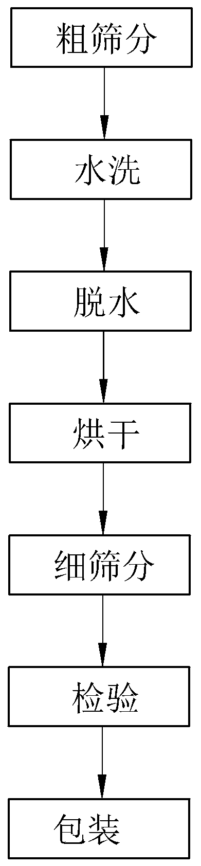
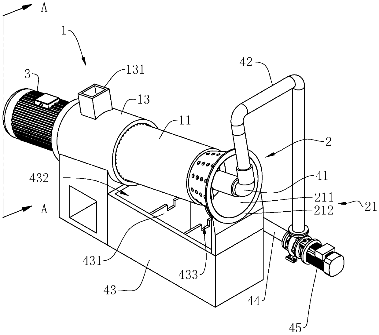
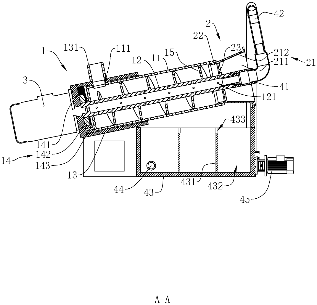
[0034] refer to figure 1 and figure 2 , is a quartz sand production process disclosed in the present invention, including coarse screening, water washing, dehydration, drying, fine screening, inspection and packaging. The coarse screening is to screen the crushed quartz sand for the first time, In the rough screening process, a linear vibrating screen is used. The mesh number of the linear vibrating screen is 20-100 mesh. Through the first screening, all the quartz sand with a particle size of 20-100 mesh is screened out; washing and dehydration The step adopts washing equipment, which includes washing device 1 and dehydration device 2. Quartz sand is added to the washing equipment from the position of washing device 1, and then flows out from the position of dehydration device 2, so that the quartz sand is washed and dehydrated in sequence, reducing the T...
PUM
 Abstract
Description
Claims
Application Information
 - R&D
- Intellectual Property
- Life Sciences
- Materials
- Tech Scout
- Unparalleled Data Quality
- Higher Quality Content
- 60% Fewer Hallucinations
Browse by: Latest US Patents, China's latest patents, Technical Efficacy Thesaurus, Application Domain, Technology Topic, Popular Technical Reports.
© 2025 PatSnap. All rights reserved.Legal|Privacy policy|Modern Slavery Act Transparency Statement|Sitemap|About US| Contact US: help@patsnap.com