
Lightning protection monitoring camera

A monitoring camera and camera technology, which is applied in the direction of image communication, TV, color TV parts, etc., can solve the problems of easily damaged lightning protection device, no picture of camera, and damaged circuit power supply of camera device, so as to avoid space and reduce cost Effect

Inactive Publication Date: 2018-04-13
WUXI XIELIAN INFORMATION TECH CO LTD
View PDF0 Cites 0 Cited by
  • Summary
  • Abstract
  • Description
  • Claims
  • Application Information

AI Technical Summary

Problems solved by technology

[0002] Existing security monitoring systems generally include data storage equipment and monitors placed indoors and camera devices placed outdoors. When a lightning strike occurs, a lightning induced current will be generated, and part of the induced current flows indoors. The indoor data storage equipment is due to the installation There are lightning protection boards that can protect against lightning, but camera devices placed outdoors usually do not have lightning protection. When lightning strikes, the circuit or power supply of the camera device will be damaged, resulting in no picture or other abnormal conditions of the camera.
[0003] Due to the complexity of the installation environment of the camera, the phenomenon of damage to the camera caused by lightning strikes is becoming more and more serious. The current camera mostly adopts the method of installing a lightning protection device to avoid lightning damage. This lightning protection method is expensive and the lightning protection device is easy to damage; On the other hand, installing a lightning protection device on the pole of the camera will increase the installation cost, which is not conducive to the use of the surveillance camera

Method used


Image

  • Lightning protection monitoring camera
  • Lightning protection monitoring camera
  • Lightning protection monitoring camera

Examples


Embodiment Construction

[0016] The following will clearly and completely describe the technical solutions in the embodiments of the present invention with reference to the accompanying drawings in the embodiments of the present invention. Obviously, the described embodiments are only some, not all, embodiments of the present invention. Based on the embodiments of the present invention, all other embodiments obtained by persons of ordinary skill in the art without making creative efforts belong to the protection scope of the present invention.

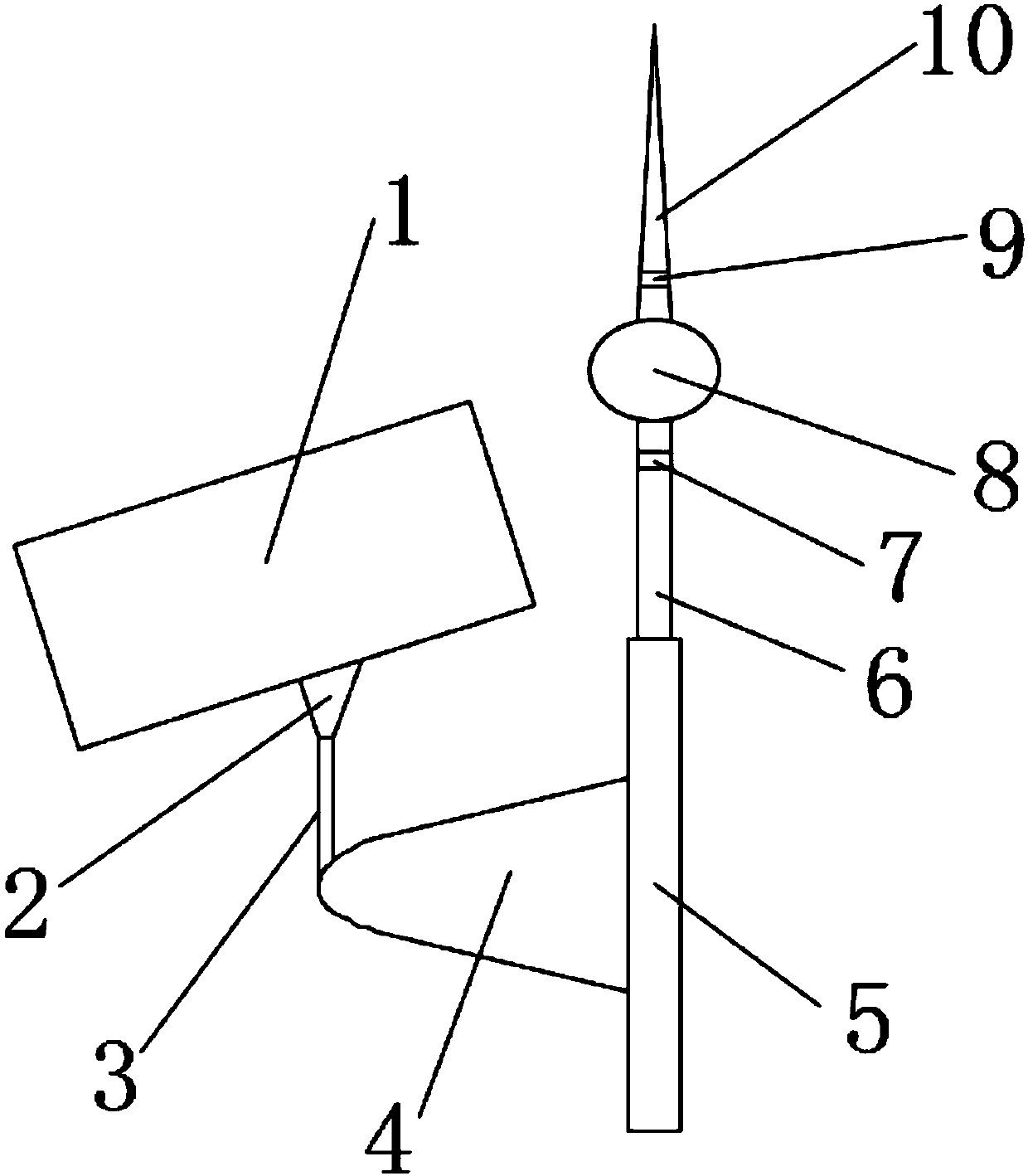
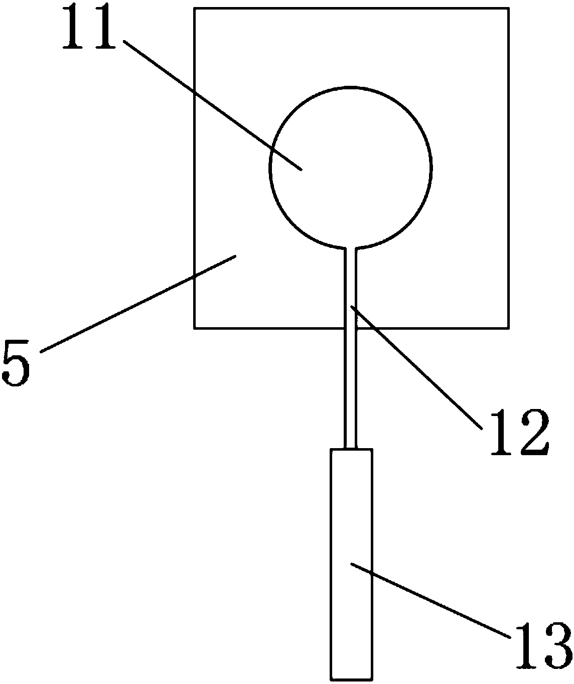
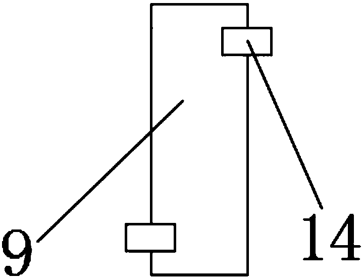
[0017] see Figure 1-3 , a lightning protection monitoring camera, comprising a camera body 1, one side of the camera body 1 is connected with a connecting rod 2, which is convenient for fixing the camera, one side of the connecting rod 2 is connected with a driving rod 3, and the driving rod One side of 3 is connected with a support rod 4, and one side of the support rod 4 is connected with a fixing base 5, which facilitates the realization of the insulation ...


PUM


Abstract

The invention discloses a lightning protection monitoring camera comprising a camera body, wherein a connection rod is connected with one side of the camera body, a drive rod is connected with one side of the connection rod, a support rod is connected with one side of the drive rod, a fixing base is connected with one side of the support rod, a guide rod is connected with one side of the fixing base, a first rotation shaft is rotationally connected with one side of the guide rod, a fixing ring is connected with one side of the first rotation shaft, a second rotation shaft is rotationally connected with one side of the fixing ring, and an air termination is connected with one side of the second rotation shaft. According to the lightning protection monitoring camera provided by the invention, the air termination and the guide rod are connected with the fixing base, so that the camera meets the lightning protection requirement during the primary installation process, without installing the arrester independently; meanwhile the air termination and the guide rod can be folded via the first rotation shaft and the second rotation shaft, the space occupied by the camera during use and installation is avoided, and the cost is effectively reduced.

Description

technical field [0001] The invention relates to the technical field of monitoring equipment, in particular to a lightning protection monitoring camera. Background technique [0002] Existing security monitoring systems generally include data storage equipment and monitors placed indoors and camera devices placed outdoors. When a lightning strike occurs, a lightning induced current will be generated, and part of the induced current flows indoors. The indoor data storage equipment is due to the installation There is a lightning protection board to protect against lightning, but camera devices placed outdoors usually do not have lightning protection. When a lightning strike occurs, the circuit or power supply of the camera device will be damaged, resulting in no picture or other abnormal conditions of the camera. [0003] Due to the complexity of the installation environment of the camera, the phenomenon of damage to the camera caused by lightning strikes is becoming more and m...

Claims


Application Information

Patent Timeline
Patent Type & Authority Applications(China)
IPC IPC(8): H04N5/225H01T19/04
CPCH01T19/04H04N23/50
Inventor 刘红灯
Owner WUXI XIELIAN INFORMATION TECH CO LTD
Learn More