Control method and device for Vienna rectifier

A control method and rectifier technology, which are applied to output power conversion devices, harmonic reduction devices, and AC networks to reduce harmonics/ripples, etc., can solve problems such as Vienna rectifier runaway, system runaway, and wrong voltage vector execution. Achieve the effect of avoiding voltage vector and maintaining system stability

Active Publication Date: 2019-09-20
天津天诚智慧能源科技有限公司
View PDF10 Cites 0 Cited by
  • Summary
  • Abstract
  • Description
  • Claims
  • Application Information

AI Technical Summary

Problems solved by technology

When a control strategy such as harmonic suppression is added to the control part of the Vienna rectifier, it is likely to cause the grid-connected voltage vector u g and grid-connected current vector i g There is a certain phase difference, and near the current switching point, the wrong voltage vector will be executed, and the system will be out of control in severe cases
[0003] However, when the grid voltage contains 5th, 7th and other low-order harmonics, if there is no targeted harmonic suppression control strategy, the input current of the Vienna rectifier will also contain harmonics of the corresponding frequency, making the grid environment worse
When the harmonic content in the grid voltage exceeds a certain range, the Vienna rectifier will enter an out-of-control state

Method used


Image

  • Control method and device for Vienna rectifier
  • Control method and device for Vienna rectifier
  • Control method and device for Vienna rectifier

Examples


Embodiment 1

[0031] Image 6 It is the control method flow chart of the Vienna rectifier of the embodiment of the present invention Figure 1 . The execution subject of this method can be the controller set in the wind turbine, such as Image 6 As shown, the method includes:

[0032] S610, in the process of controlling the current inner loop of the Vienna rectifier connected to the grid, monitor the grid voltage and grid current in real time;

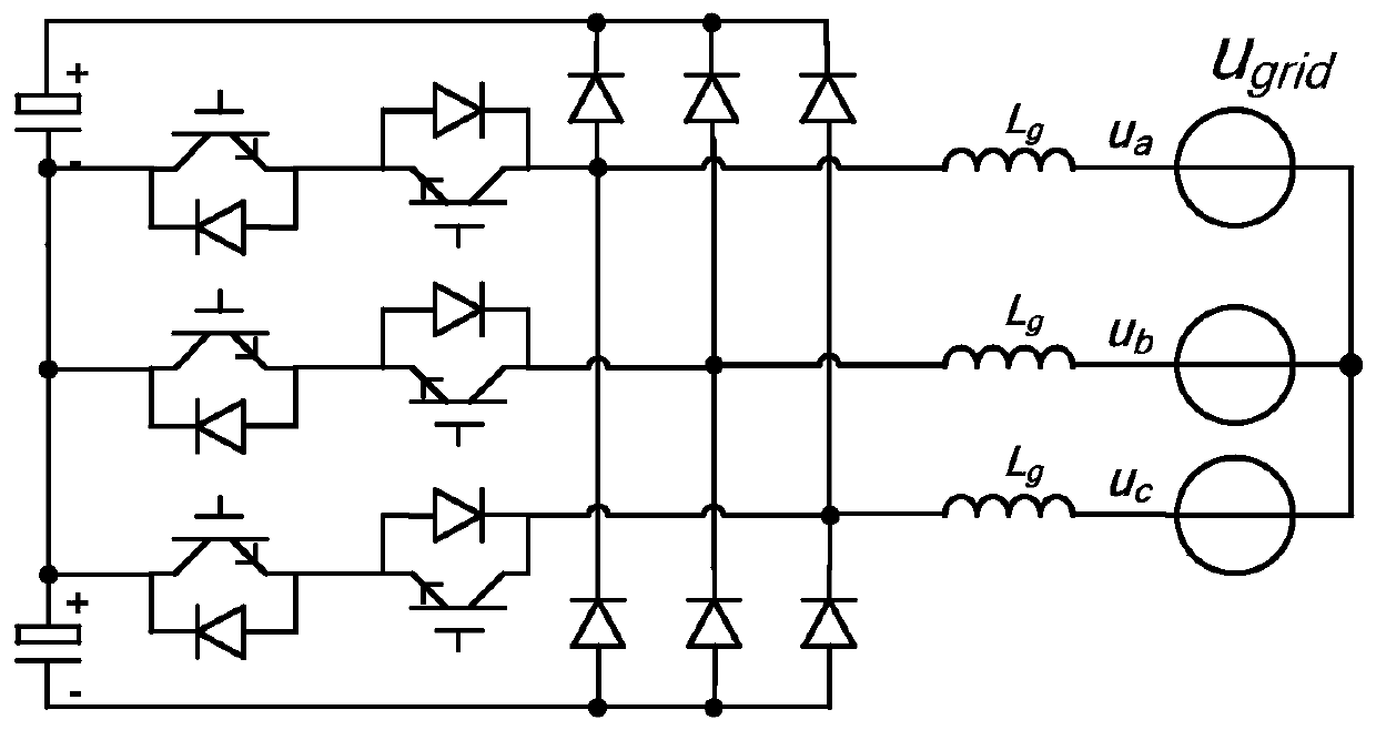
[0033] If shown in 5, collect the three-phase grid voltage u a , u b , u c (abbreviated "u abc ”) and three-phase grid current i a i b i c (abbreviated "i abc ”), the three-phase grid voltage u a , u b , u c Through the PLL phase-locked loop processing, the direct-axis voltage u in the rotating coordinate system is obtained gd and quadrature voltage ugq , and the rotation angle θ of the rotated coordinates g ;The three-phase grid current i a i b i c Through the transformation from the three-phase stationary coordinate system to the...

Embodiment 2

[0041] Figure 7 It is the control method flow chart of the Vienna rectifier of the embodiment of the present invention Figure II In this embodiment, on the basis of the method described in Embodiment 6, the control process of the zero-crossing area of ​​the grid current and the non-zero-crossing area of ​​the grid current is described in detail. Such as Figure 7 As shown, the control method of the Vienna rectifier includes the following steps:

[0042] S710, during the control process of the current inner loop of the Vienna rectifier connected to the grid, monitor the grid voltage and grid current in real time; the content of step S710 is similar to that of step S610.

[0043] Specifically, such as Figure 8 shown, which is Figure 5 Schematic diagram of the PLL phase-locked loop transfer function algorithm, ω g is the grid vector speed, θ g is the initial angle of the grid voltage vector. The bandwidth of the phase-locked loop should be limited low, and the shear fr...

Embodiment 3

[0067] Figure 9 It is a structural representation of the control device of the Vienna rectifier according to the embodiment of the present invention Figure 1 , the control unit of the Vienna rectifier can be used to perform Image 6 The method steps shown. Such as Figure 9 As shown, the control device of the Vienna rectifier includes:

[0068] The data monitoring module 910 is used to monitor the grid voltage and grid current in real time during the control process of the current inner loop of the Vienna rectifier connected to the grid;

[0069] The first data adjustment module 920 is used to adjust the given value of the quadrature axis current in the current inner loop if there is a phase difference between the grid voltage and the grid current, and the phase of the grid voltage belongs to the zero-crossing area of ​​the grid current, so that using The adjusted quadrature axis current given value controls the Vienna rectifier, so that the phase of grid current and gri...


PUM


Abstract

The embodiment of the invention provides a method and apparatus for controlling a Vienna rectifier. The method comprises: when current inner-loop controlling is carried out on a Vienna rectifier in agrid-connected state, a grid voltage and a grid current are monitored in real time; if a phase difference exists between the grid current and the grid voltage and the phase of the grid voltage belongsto a zero-crossing region of the grid current, a quadrature axis current given value in the current inner loop is adjusted, so that the Vienna rectifier is controlled by using the adjusted quadratureaxis current given value and thus the phase of the grid current is identical with that of the grid voltage. Therefore, when a certain phase difference exists between the grid voltage vector and the grid current vector, execution of a wrong voltage vector near a current switching point is avoided, so that the system stability is kept.

Description

technical field [0001] The invention relates to the technical field of wind power, in particular to a control method and device for a Vienna rectifier. Background technique [0002] The traditional control of the Vienna rectifier is limited by the small number of controllable components, so it can only achieve the same phase rectification as the grid voltage. figure 1 The schematic diagram of the circuit after the Vienna rectifier is incorporated into the grid, figure 2 It is a schematic diagram of a vector coordinate system involved in the present invention, including a two-term rotating coordinate system and a three-phase stationary coordinate system, image 3 for figure 1 Grid current i in the corresponding three-phase stationary coordinate system a i b i c The periodic change diagram of , such as image 3 As shown, when the grid-connected current phase is located in the shaded area shown in the figure, due to the a-phase current i a Inflow, b-phase current i b ,...

Claims


Application Information

Patent Timeline
Patent Type & Authority Patents(China)
IPC IPC(8): H02M7/217H02J3/01
CPCH02J3/01H02M7/217Y02E40/40
Inventor 姜鑫王川商二松
Owner 天津天诚智慧能源科技有限公司
Why Eureka
Try Eureka