Forging mold

A technology of die and die base, which is applied in the direction of manufacturing tools, forging/pressing/hammer devices, forging/pressing/hammering machines, etc., can solve the problems of waste of resources and complicated structure of ejector devices, and achieve energy saving and simple structure. Effect

Inactive Publication Date: 2018-05-04
李永萍
View PDF5 Cites 2 Cited by
  • Summary
  • Abstract
  • Description
  • Claims
  • Application Information

AI Technical Summary

Problems solved by technology

After the product forging is completed, the product needs to be taken out. In the prior art, a power device is added to eject the product. This method makes the structure of the ejection device complicated, and the power device used more often causes a waste of resources.

Method used


Image

  • Forging mold

Examples


Embodiment Construction

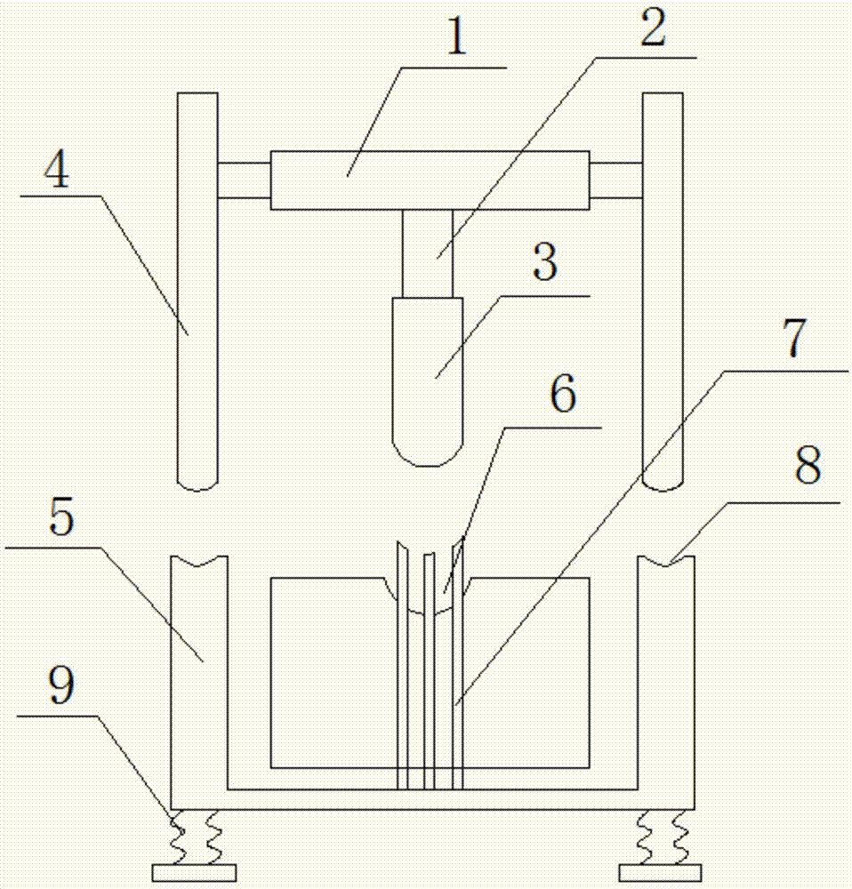
[0012] The present invention will be further described below in conjunction with the accompanying drawings and embodiments.

[0013] figure 1 Among them, a forging die includes an upper mold base and a lower mold base that cooperate with each other. The upper mold base includes a punch mounting base 1, and the punch mounting base 1 is connected with a punch 3 through a connecting rod 2. The lower mold base is provided with There is a forging groove 6 matched with the punch 3, and an ejector device is provided on the lower mold base, and the ejector device includes a ejector rod 7 that runs through the forging groove 6, and the ejector rod 7 is connected with a driven rod 5, and the punch mounting seat 1 is connected with the active rod 4 that is compatible with the driven rod 5, and the lower end of the driven rod 5 is also connected with a return spring 9.

[0014] There are three push rods 7 and they are triangularly distributed. One end of any push rod 7 extends out of the...


PUM


Abstract

A forging mold comprises an upper mold seat and a lower mold seat which are matched with each other. The upper mold seat comprises a punch mounting seat (1). A punch (3) is connected to the punch mounting seat (1) through a connecting rod (2). A forging groove (6) matched with the punch (3) is formed in the lower mold seat. An ejection device is arranged on the lower mold seat. The ejection devicecomprises ejector rods (7) penetrating the forging groove (6). The ejector rods (7) are connected with driven rods (5). The punch mounting seat (1) is connected with driving rods (4) matched with thedriven rods (5). The lower ends of the driven rods (5) are further connected with reset springs (9). The forging mold has the beneficial effects that ejection is more automatic by using cooperation of the upper mold seat and the lower mold seat during forging, and a power device required during ejection is omitted, so that the structure is simpler, and energy is saved.

Description

technical field [0001] The invention relates to the field of forging machinery, in particular to a forging die. Background technique [0002] Forging dies means that the metal is first heated to become a liquid or softened state. Put it into the mold again, and form it at one time through the closing and closing of the upper and lower molds of the mold, sometimes requiring multiple times. After the product forging is completed, the product needs to be taken out. In the prior art, a power device is added to eject the product. This method makes the structure of the ejector device complicated, and more power devices are used, which also causes a waste of resources. Contents of the invention [0003] The purpose of the present invention is to solve the deficiencies of the prior art and provide a forging die with automatic ejection function. [0004] The technical solution adopted by the present invention to solve the above problems is: a forging die, including an upper mold ...

Claims


Application Information

Patent Timeline
Patent Type & Authority Applications(China)
IPC IPC(8): B21J13/02B21J13/14
CPCB21J13/02B21J13/14
Inventor 李永萍
Owner 李永萍
Why Eureka
Try Eureka