Auxiliary unmanned fire-extinguishing robot for ship engine room

A fire-fighting robot, engine room technology, applied in fire rescue and other directions, can solve problems such as fire-fighting danger

Inactive Publication Date: 2021-06-08
李田浩
View PDF0 Cites 0 Cited by
  • Summary
  • Abstract
  • Description
  • Claims
  • Application Information

AI Technical Summary

Problems solved by technology

[0002] Fire-fighting equipment refers to the equipment used for fire extinguishing, fire prevention and fire accidents. It is used for professional fire-fighting equipment. The most commo

Method used


Image

  • Auxiliary unmanned fire-extinguishing robot for ship engine room
  • Auxiliary unmanned fire-extinguishing robot for ship engine room
  • Auxiliary unmanned fire-extinguishing robot for ship engine room

Examples


Embodiment 1

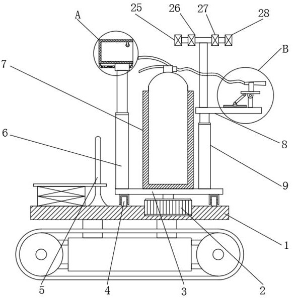
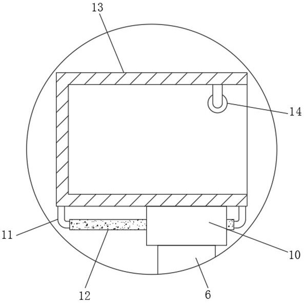
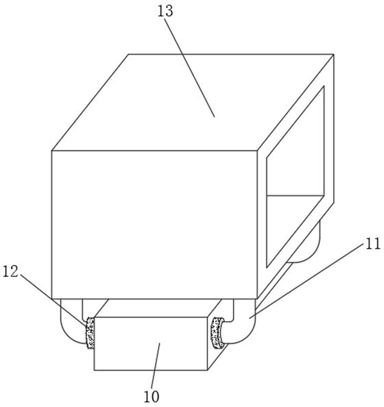
[0031] refer to Figure 1-4 , an auxiliary unmanned fire-fighting robot for a ship engine room, comprising a moving seat 1, a mounting groove is opened on the top outer wall of the moving seat 1, and a stepping motor 2 is arranged on the inner wall of the mounting groove, and a turntable is arranged at one end of the output shaft of the stepping motor 2 3. The top outer wall of the turntable 3 is provided with a fixed cylinder 7, and the position close to one side of the top outer wall of the turntable 3 is fixedly connected with the first electric telescopic rod 6, and one end of the piston of the first electric telescopic rod 6 is provided with a fixed block 10, the fixed block The outer wall of 10 is provided with a sliding hole, and the inner wall of the sliding hole is slidably provided with a sliding rod 11, the top of the sliding rod 11 is fixedly connected with the limit frame 13, and the outer wall of the top of the turntable 3 is fixedly connected with a second electr...

Embodiment 2

[0041] refer to Figure 5-6 , an auxiliary unmanned fire-fighting robot for a ship engine room. Compared with Embodiment 1, this embodiment also includes a sleeve 21 fixedly connected to the outer walls of the mobile seat 1, and a spring 22 fixedly connected to the inner wall of one side of the sleeve 21. , and one end of the spring 22 is provided with a telescopic rod 23, and one end of the telescopic rod 23 is provided with a protective plate 24.

[0042] Working principle: When in use, when the fire extinguishing robot hits foreign objects during the movement, the protective plate 24 will compress the spring 22 in the sleeve 21, which can play a certain buffering effect and effectively protect the fire extinguishing robot. better.


PUM


Abstract

The invention discloses an auxiliary unmanned fire-extinguishing robot for a ship engine room. The robot comprises a movable seat, wherein a mounting groove is formed in the outer wall of the top of the movable seat, a stepping motor is arranged on the inner wall of the mounting groove, a rotary disc is arranged at one end of an output shaft of the stepping motor, a fixed cylinder is arranged on the outer wall of the top of the rotary disc, a first electric telescopic rod is fixedly connected to the position, close to one side, of the outer wall of the top of the rotary disc, a fixed block is arranged at one end of a piston of the first electric telescopic rod, a sliding hole is formed in the outer wall of the fixed block, a sliding rod is slidably arranged on the inner wall of the sliding hole, a limiting frame is fixedly connected to the top end of the sliding rod, and a second electric telescopic rod is fixedly connected to the position, close to the other side, of the outer wall of the top of the rotary disc. According to the robot, a fire extinguishing spray can be automatically sprayed out, the using effect is better, the fire extinguishing height can be adjusted, the fire extinguishing direction also can be adjusted, and therefore the flexibility of the robot in use is effectively improved.

Description

technical field [0001] The invention relates to the technical field of fire-fighting equipment, in particular to an unmanned fire-fighting robot assisted by a ship engine room. Background technique [0002] Fire-fighting equipment refers to the equipment used for fire extinguishing, fire prevention and fire accidents. It is used for professional fire-fighting equipment. The most common fire-fighting equipment is mainly a fire extinguisher. It is very dangerous for ordinary personnel to carry out fire extinguishing in the engine room of the ship without any protective equipment. [0003] At present, when a fire breaks out in the engine room of a ship, in order to minimize the damage and avoid the situation where ordinary personnel extinguish the fire without any protection, an unmanned fire extinguishing robot can be used to assist in extinguishing the fire. Therefore, it is urgent to design a The ship engine room assists the unmanned fire-fighting robot to solve the above p...

Claims


Application Information

Patent Timeline
IPC IPC(8): A62C27/00A62C13/78A62C31/03A62C37/38A62C3/10
CPCA62C3/10A62C13/78A62C27/00A62C31/03A62C37/38
Inventor 李田浩寇岩
Owner 李田浩
Why Eureka
Try Eureka