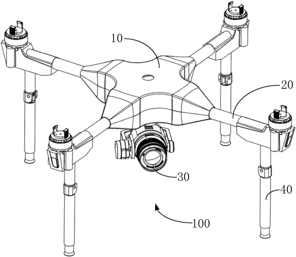
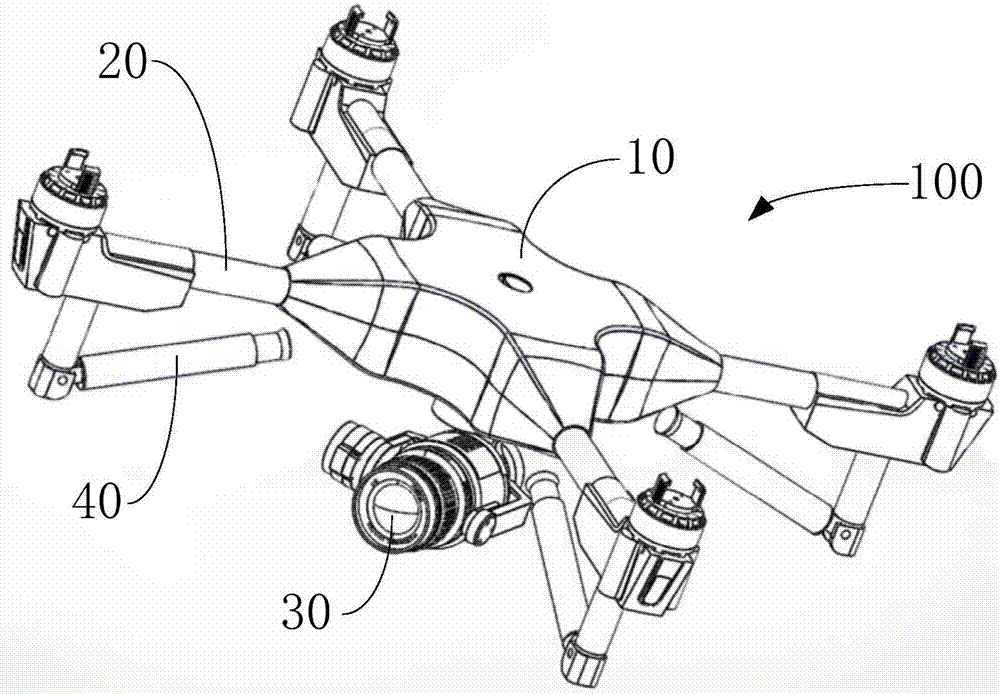
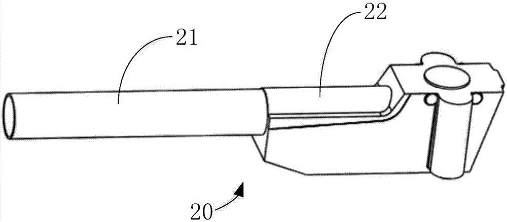
[0031] In order to facilitate the understanding of the present invention, the present invention will be described in more detail below with reference to the drawings and specific embodiments. It should be noted that when an element is expressed as being "fixed to" another element, it can be directly on the other element, or there can be one or more elements in between. When an element is said to be "connected" to another element, it can be directly connected to the other element, or there may be one or more intervening elements in between. The terms "vertical", "horizontal", "left", "right", "upper", "lower", "inner", "outer", "bottom", etc. used in this manual indicate the orientation or positional relationship Based on the orientation or positional relationship shown in the drawings, it is only for the convenience of describing the present invention and simplifying the description, rather than indicating or implying that the device or element referred to must have a specific orientation, be constructed and operated in a specific orientation, and therefore cannot It is understood as a limitation of the present invention. In addition, the terms "first", "second", etc. are only used for descriptive purposes, and cannot be understood as indicating or implying relative importance.
[0032] Unless otherwise defined, all technical and scientific terms used in this specification have the same meaning as commonly understood by those skilled in the technical field of the present invention. The terms used in the specification of the present invention in this specification are only for the purpose of describing specific embodiments, and are not used to limit the present invention. The term "and/or" as used in this specification includes any and all combinations of one or more related listed items.
[0033] In addition, the technical features involved in the different embodiments of the present invention described below can be combined with each other as long as they do not conflict with each other.
[0034] Such as figure 1 As shown, one embodiment of the present invention provides an unmanned aerial vehicle 100, which includes a fuselage 10, an arm 20, a camera device 30, and a landing gear 40. Wherein, one end of the machine arm 20 is fixed to the fuselage 10; the camera device 30 is installed under the fuselage 21 for taking images; the landing gear 40 is installed on the other end of the machine arm 20, The landing gear 40 can be rotated and folded relative to the arm 20 (the folded state is as figure 2 Shown) or expanded (the expanded state is as figure 1 Shown). When the landing gear 40 is retracted, the distance between the landing end of the landing gear 40 and the bottom of the fuselage 21 is smaller than the distance between the camera device 30 and the bottom of the fuselage 21, so that the landing can be prevented. The landing gear 40 shields the camera device 30 mounted on the UAV 100, thereby improving the shooting effect of the camera device 30.
[0035] The unmanned aerial vehicle 100 can be a single-rotor unmanned aerial vehicle, a dual-rotor unmanned aerial vehicle, a quad-rotor unmanned aerial vehicle, or a hexa-rotor unmanned aerial vehicle, etc. In this embodiment, the unmanned aerial vehicle 100 is a four-rotor unmanned aerial vehicle. As an example, the specific structure of the UAV 100 will be described in detail.
[0036] Such as figure 1 with 2 As shown, the number of the arm 20 and the landing gear 40 are both four, and one end of the arm 20 is fixed to the fuselage 10. Specifically, one ends of the four arms 20 are all fixedly connected to the body 10. The fuselage 10 and the machine arm 20 are approximately in a cross shape, that is, two non-adjacent machine arms 20 are located on the same straight line, and two adjacent machine arms 20 are perpendicular to each other. The landing gear 40 is installed at the other end of the arm 20 away from the fuselage 10. The four landing gears 40 correspond to the four aircraft arms 20 one-to-one (that is, each landing gear 40 is mounted on one aircraft arm 20).
[0037] Such as image 3 with 4 As shown, the arm 20 includes a connecting arm 21 and a mounting base 22. The connecting arm 21 is a long straight rod, one end of which is fixedly connected to the body 10, and the mounting base 22 is mounted on the connecting arm. 21 at the other end.
[0038] The mounting base 22 includes a bearing surface 221 for installing a power device (the power device includes a propeller and a motor, which is used to provide flight power to the UAV 100), and a connection for connecting with the connecting arm 21 面222和Installation surface 223. The bearing surface 221 and the mounting surface 223 are respectively located on two opposite sides of the mounting seat 22, and the connecting surface 222 is located on a side surface perpendicular to the mounting surface 223. The connecting surface 222 is provided with a connecting hole 2221 for connecting with the connecting arm 21, and the other end of the connecting arm 21 away from the body 10 is inserted into the connecting hole 2221, so that the mounting seat 22 is fixed. At the other end of the connecting arm 21 away from the body 10. The mounting surface 223 is provided with a receiving groove 2231.
[0039] Such as Figure 5 with 6 As shown, the landing gear 40 includes a driving device 41, a gear transmission mechanism 42, a screw transmission mechanism 43, a first sleeve 44, and a first pivotal connection provided at the connection between the arm 20 and the landing gear 40. The member 45, the second pivotal member 46, the second sleeve 47 and the support rod 48. The driving device 41 is received in the receiving slot 2231 and has a rotating shaft 411 (such as Image 6 Shown). The support rod 48 is made of elastic material.
[0040] Such as Figure 7 As shown, the gear transmission mechanism 42 includes a rotating shaft group and a gear group. The rotating shaft group (not marked in the figure) includes a first rotating shaft (not marked in the figure), a second rotating shaft (not marked in the figure), a third rotating shaft (not marked in the figure) and a fourth rotating shaft (not marked in the figure). The gear set (not shown in the figure) includes a first gear 4221, a second gear 4222, a third gear 4223, a fourth gear 4224, a fifth gear 4225, a sixth gear 4226, a seventh gear 4227, and an eighth gear 4228. The first gear 4221 is fixed on the rotating shaft 411, and the driving device 41 can drive the first gear 4221 to rotate. The second gear 4222 is fixed on the first rotating shaft (not shown in the figure) and meshes with the first gear 4221. The third gear 4223 is fixed on the first rotating shaft (not shown in the figure). The fourth gear 4224 is fixed on the second rotating shaft (not shown in the figure) and meshes with the third gear 4223. The fifth gear 4225 is fixed on the second rotating shaft (not shown in the figure). The sixth gear 4226 is fixed on the third rotating shaft (not shown in the figure) and meshes with the fifth gear 4225. The seventh gear 4227 is fixed on the third rotating shaft (not shown in the figure). The eighth gear 4228 is fixed on the fourth shaft (not shown in the figure) and meshes with the seventh gear 4227. The number of teeth of the first gear 4221 is less than the number of teeth of the second gear 4222, the number of teeth of the third gear 4223 is less than the number of teeth of the second gear 4222, and the number of teeth of the third gear 4223 is less than that of the fourth gear The number of teeth of the fifth gear 4225 is smaller than the number of teeth of the fourth gear 4224, and the number of teeth of the fifth gear 4225 is smaller than the number of teeth of the sixth gear 4226. The third rotating shaft (not shown in the figure) is connected to the screw drive mechanism 43. Since the transmission ratio between every two meshing gears is greater than one, the total transmission ratio of the gear transmission mechanism 42 is much greater than one. The output torque of the gear transmission mechanism 42 is equal to the torque of the driving device 41 (that is, the input torque of the gear transmission mechanism 42) multiplied by the total transmission ratio of the gear transmission mechanism 42. It can be seen that the gear transmission mechanism 42 has the effect of amplifying the torque of the driving device 41.
[0041] The sixth gear 4226 and the seventh gear 4227 are exactly the same (that is, the number of teeth, the modulus, and the index circle diameter of the sixth gear 4226 and the seventh gear 4227 are equal). The fifth gear 4225 and the eighth gear 4228 are completely the same (that is, the number of teeth, the modulus, and the index circle diameter of the fifth gear 4225 and the eighth gear 4228 are all equal). The sixth gear 4226 and the seventh gear 4227 are fixed on the third rotating shaft (not shown in the figure), the fifth gear 4225 drives the sixth gear 4226 to rotate, and the third rotating shaft (not shown in the figure) ) And the seventh gear 4227 fixed on the third rotating shaft (not shown in the figure) rotate together, and the eighth gear 4228 rotates together. Based on the above structure, during the rotation of the third rotating shaft (not shown in the figure), the sixth gear 4226 and the seventh gear 4227 respectively interact with the fifth gear 4225 and the eighth gear located on both sides of the third rotating shaft (not shown in the figure). The meshing of the gear 4228 can make the force of the third rotating shaft (not shown in the figure) more balanced and the rotation more stable.
[0042] It can be understood that in some other embodiments, when the torque of the driving device 41 is sufficiently large, the gear transmission mechanism 42 can be omitted, that is, the screw transmission mechanism 43 is directly connected to the driving device 41.
[0043] In this embodiment, the driving device 41 is specifically a motor. It is understandable that, in order to precisely control the angle of rotation of the support rod 48 relative to the first sleeve 44, the driving device 41 may specifically be a steering gear, and the gear transmission mechanism 42 may be omitted. The rod transmission mechanism 43 is directly connected.
[0044] Such as Picture 8 As shown, the screw transmission mechanism 43 includes a screw 431 fixedly connected to a third rotating shaft (not shown in the figure), a connecting member 432, a rotating gear 433 and a pin 434. One end of the connecting member 432 is threadedly connected with the screw rod 431, and the other end is meshed with the rotating gear 433. The rotating gear 433 is fixed to the pin shaft 434. When the screw rod 431 rotates, the connecting member 432 makes a linear reciprocating movement along the screw rod 431. As the connecting member 432 performs linear reciprocating motion, the rotating gear 433 can be driven to rotate around the pin shaft 434.
[0045] Specific, such as Picture 9 As shown, the connecting member 432 includes a connecting shaft 4321, a fixed portion 4322, and a rack 4323. The fixing portion 4322 is generally U-shaped, and the connecting shaft 4321 is disposed on the open end (ie, the U-shaped open end) of the fixing portion 4322. One end of the rack 4323 is fixed to the other end of the fixing portion 4322. The middle part of the connecting shaft 4321 is provided with a threaded hole 43211 along the axial direction perpendicular to the connecting shaft 4321, and the threaded rod 431 is screwed into the threaded hole 43211, so that the threaded rod 431 and the connecting shaft 4321 Threaded connection. The rack 4323 meshes with the rotating gear 433.
[0046] It is understandable that, in some other embodiments, the screw drive mechanism 43 can be replaced by other transmission mechanisms that have the function of converting linear motion into rotational motion, such as a worm gear mechanism, a crank slider mechanism, and the like.
[0047] See again figure 1 with Figure 5 One end of the first sleeve 44 is butted with the accommodating groove 2231 and is fixedly connected to the mounting seat 22, and the other end is fixedly connected to the first pivot member 45. The first sleeve 44 is provided with a through hole 441 along the axial direction, and the screw rod 431 and the connecting member 432 are both located in the through hole 441.
[0048] The first pivot member 45 and the second pivot member 46 are connected by the pin shaft 434, and the first pivot member 45 is hinged with the pin shaft 434, and the second pivot member 46 is connected with the pin shaft 434. The pin shaft 434 is fixedly connected.
[0049] One end of the second sleeve 47 is fixedly connected to the second pivotal member 46, and the other end is connected to the support rod 48. The second sleeve 47 is provided with a blind hole (not shown) along the axial direction, and the opening of the blind hole is located at the other end surface of the second sleeve 47. One end of the support rod 48 is inserted into the blind hole and can move along the blind hole. The undercarriage 40 also includes an elastic abutting member 49, the elastic abutting member 49 is located in the blind hole, and one end of the elastic abutment member 49 abuts the bottom surface of the blind hole. The other end abuts against the end surface of one end of the support rod 48. The other end of the support rod 48 is used for contacting the ground or the surface of other objects when the UAV 100 is landing, so as to support the UAV 100. When the other end of the support rod 48 is under pressure, the elastic abutment 49 can be compressed through the conduction of the support rod 48, so as to buffer the impact force transmitted by the support rod 48, thereby causing the UAV 100 to land. It is more gentle to prevent damage to other parts or equipment on the UAV 100 from impact.
[0050] It can be understood that, in some other embodiments, the first pivotal member 45, the second pivotal member 46, the second sleeve 47 and the elastic resisting member 49 may be omitted. The support rod 48 is hinged to the first sleeve 44 through the pin shaft 434, and the support rod 48 is fixedly connected to the pin shaft 434.
[0051] It can be understood that in some other embodiments, the first pivotal member 45 and the second pivotal member 46 may be omitted. The second sleeve 47 is hinged with the first sleeve 44 through the pin shaft 434, and the second sleeve 47 is fixedly connected with the pin shaft 434.
[0052] It can be understood that in some other embodiments, the second sleeve 47 and the elastic resisting member 49 can be omitted. One end of the support rod 48 is directly and fixedly connected with the second pivotal member 46.
[0053] Compared with the prior art, the present invention provides a landing gear 40 and an unmanned aerial vehicle 100 having the landing gear 40. The landing gear 40 includes: a driving device 41, a transmission mechanism 43 that can convert linear motion into a rotational motion, a first sleeve 44, and a support rod 48, wherein the transmission mechanism 43 is connected to the driving device 41; The transmission mechanism 43 penetrates the first sleeve 44; the support rod 48 is hinged to the first sleeve 44, and the driving device is connected to the support rod through the transmission mechanism and can drive the support rod to face each other The first sleeve is rotated and folded or unfolded. During the flight of the UAV, the support rod can be folded and stowed to prevent the support rod of the landing gear from blocking the camera device installed on the UAV and improve the shooting effect of the camera device.
[0054] The above are only the embodiments of the present invention, and do not limit the scope of the present invention. Any equivalent structure or equivalent process transformation made by using the content of the description and drawings of the present invention, or directly or indirectly applied to other related technologies In the same way, all fields are included in the scope of patent protection of the present invention.