
A bone conduction earphone mounted on sunglasses

A bone conduction earphone and bone conduction vibrator technology, applied in earphone/earphone accessories, earphone manufacturing/assembly, on-ear/over-ear earphones, etc., to achieve the effect of good sound effect, comfortable wearing and reducing audio loss

Active Publication Date: 2019-12-10
SUZHOU YOKO BCT ELECTRONICS
View PDF7 Cites 0 Cited by
  • Summary
  • Abstract
  • Description
  • Claims
  • Application Information

AI Technical Summary

Problems solved by technology

[0005] The technical problem to be solved by the present invention is: in order to solve the technical problem of a series of defects in the existing bone conduction earphones installed in sunglasses, to provide a bone conduction earphone installed in sunglasses

Method used


Image

  • A bone conduction earphone mounted on sunglasses
  • A bone conduction earphone mounted on sunglasses
  • A bone conduction earphone mounted on sunglasses

Examples


Embodiment 1

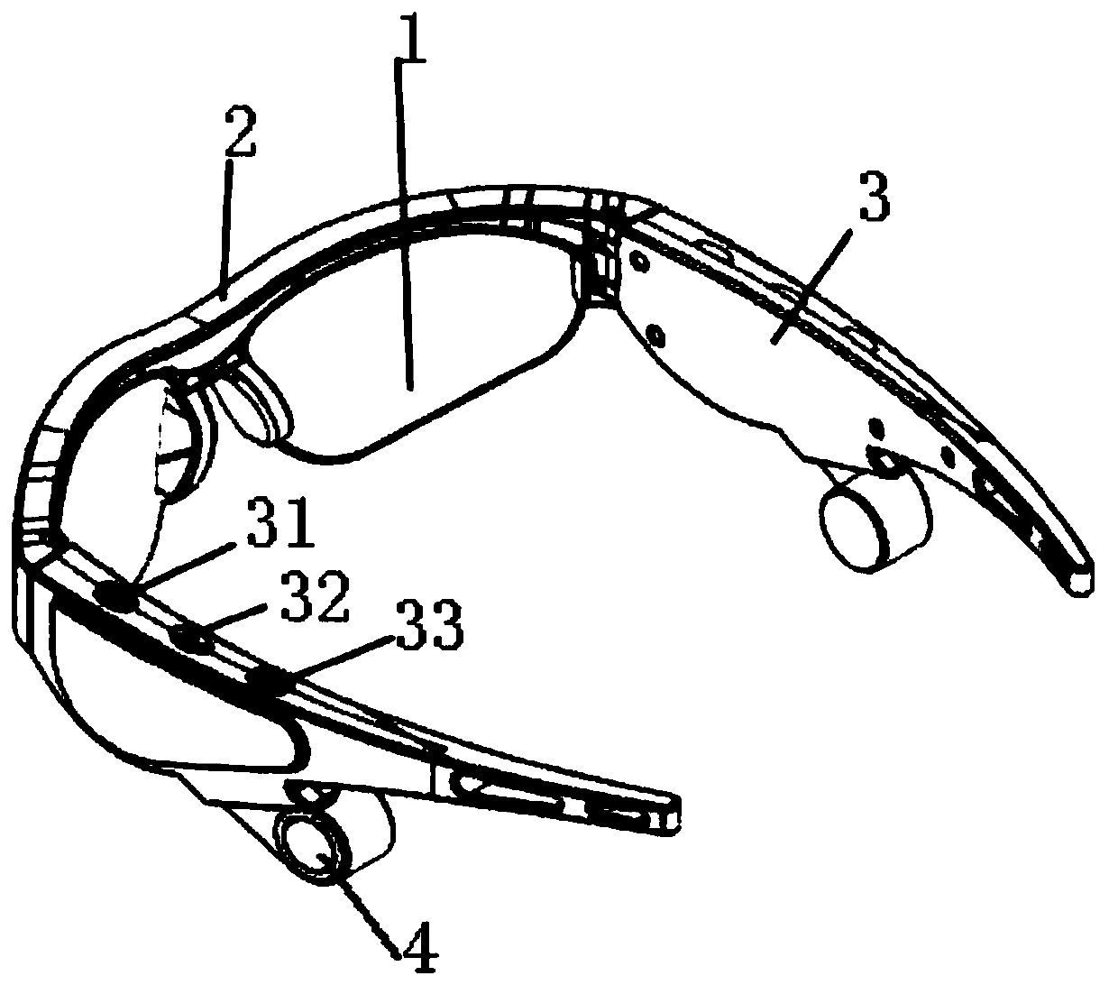
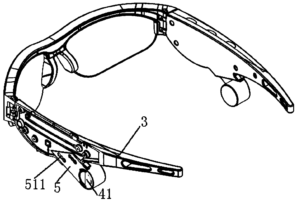
[0031] This embodiment provides a kind of sunglass with bone conduction earphone, such as figure 1 and figure 2 As shown, it includes left and right two lenses 1, a lens holder 2 for fixing the two lenses 1, two left and right temples 3 that are movably installed at the left and right ends of the lens holder 2, and a bone connected to the temples 3. The conduction earphone 4, the bone conduction earphone 4 can be arranged on one side of the temple 3, or one bone conduction earphone 4 can be arranged on each of the left and right temples 3.

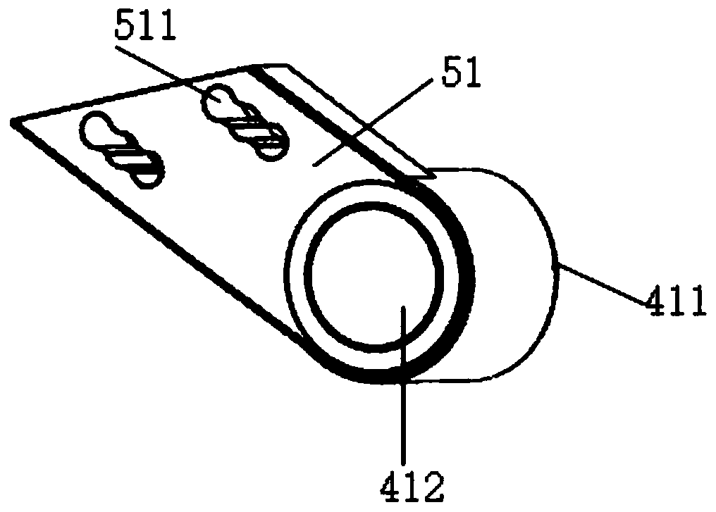
[0032] Such as figure 2 As shown, the temple 3 is connected to the bone conduction earphone 4 through a connecting structure 5, the connecting structure 5 includes a connecting plate 51 with a guide hole 511 fixed on the bone conduction earphone, located on the temple 3 The connecting groove for the connecting plate 51 to extend into, and the protruding rod (not shown in the figure) extending into the guide hole 511 located in the conn...

Embodiment 2

[0040] This embodiment provides a bone conduction earphone installed on sunglasses. The bone conduction earphone 4 includes a bone conduction vibrator and a bone conduction vibrator fixing structure 41 for generating mechanical vibrations according to audio signals and passing the mechanical vibrations through the skull The transmission to the inner ear enables the user to hear the sound.

[0041] Preferably, as Figure 4 As shown, the bone conduction vibrator fixing structure 41 is a front cover 411 and a rear cover 412 bonded together;

[0042]The rear cover 412 includes a rear cover cylinder 4121 opening toward the front cover 411, a connecting portion 4122 arranged on the cylinder wall of the rear cover cylinder 4121 perpendicular to the cylinder wall of the rear cover cylinder 4121 and located on The outer edge portion 4123 on the outer side of the connecting portion 4122 is flush with the bottom end surface of the connecting portion 4122, and the outer edge portion 4123...


PUM


Abstract

The invention relates to a bone conduction earphone mounted on sunglasses, comprising a bone conduction vibrator and a bone conduction vibrator fixing structure, wherein the bone conduction vibrator fixing structure comprises an upper fixed body and a lower fixed body bonded to each other, and vibrators are arranged and adhered between a disc-shaped end cover of the upper fixed body, an inner cylinder of the upper fixed body and a disc-shaped bottom cover of the lower fixed body, a cylinder of the lower fixed body; the inner cylinder of the upper fixed body extends into the cylinder of the lower fixed body and is adhered to the cylinder of the lower fixed body, a gap is formed between the inner cylinder of the upper fixed body and the disc-shaped bottom cover, and the outer edge of an outer cylinder of the upper fixed body is adhered to the outer edge part of the disc-shaped bottom cover. According to the bone conduction earphone mounted on the sunglasses disclosed by the invention, the vibrators are firmly mounted in the bone conduction vibrator fixing structure, and thus the bone conduction earphone has a good overall sound effect in all frequency bands, can reduce the audio loss, and is comfortable to wear.

Description

technical field [0001] The invention relates to a bone conduction earphone mounted on sunglasses, belonging to the technical field of wearable devices. Background technique [0002] Most of the currently used sunglasses are simple in design and have a single function, and are mainly used for wearing outdoors or driving to block strong light. However, this type of sunglasses does not have the function of earphones. Sunglasses to listen to music or answer calls, especially when a call comes in, the user cannot immediately pick up the mobile phone or earphones to answer the call, if the earphones are installed in the worn sunglasses, the driver can answer the call conveniently and safely. Therefore, need a kind of sunglasses that can integrate earphone and anti-ultraviolet. [0003] Although there are also sunglasses with earphones in the prior art, most of them are earplug earphones through air conduction. This earplug earphone transmits sound to the eardrum through air vibra...

Claims


Application Information

Patent Timeline
Patent Type & Authority Patents(China)
IPC IPC(8): H04R1/10
CPCH04R1/1008H04R1/1058
Inventor 张小成
Owner SUZHOU YOKO BCT ELECTRONICS
Learn More