Apparatus and method for producing sound
a technology of apparatus and sound, applied in the field of apparatus and method for producing sound, can solve the problems of complex operation of successful design of distributed mode loudspeakers, inability to reproduce faithfully, and inability to produce the lowest frequencies of music, etc., to achieve reasonable cost, enhance sound, and improve sound spaciousness
- Summary
- Abstract
- Description
- Claims
- Application Information
AI Technical Summary
Benefits of technology
Problems solved by technology
Method used
Image
Examples
first embodiment
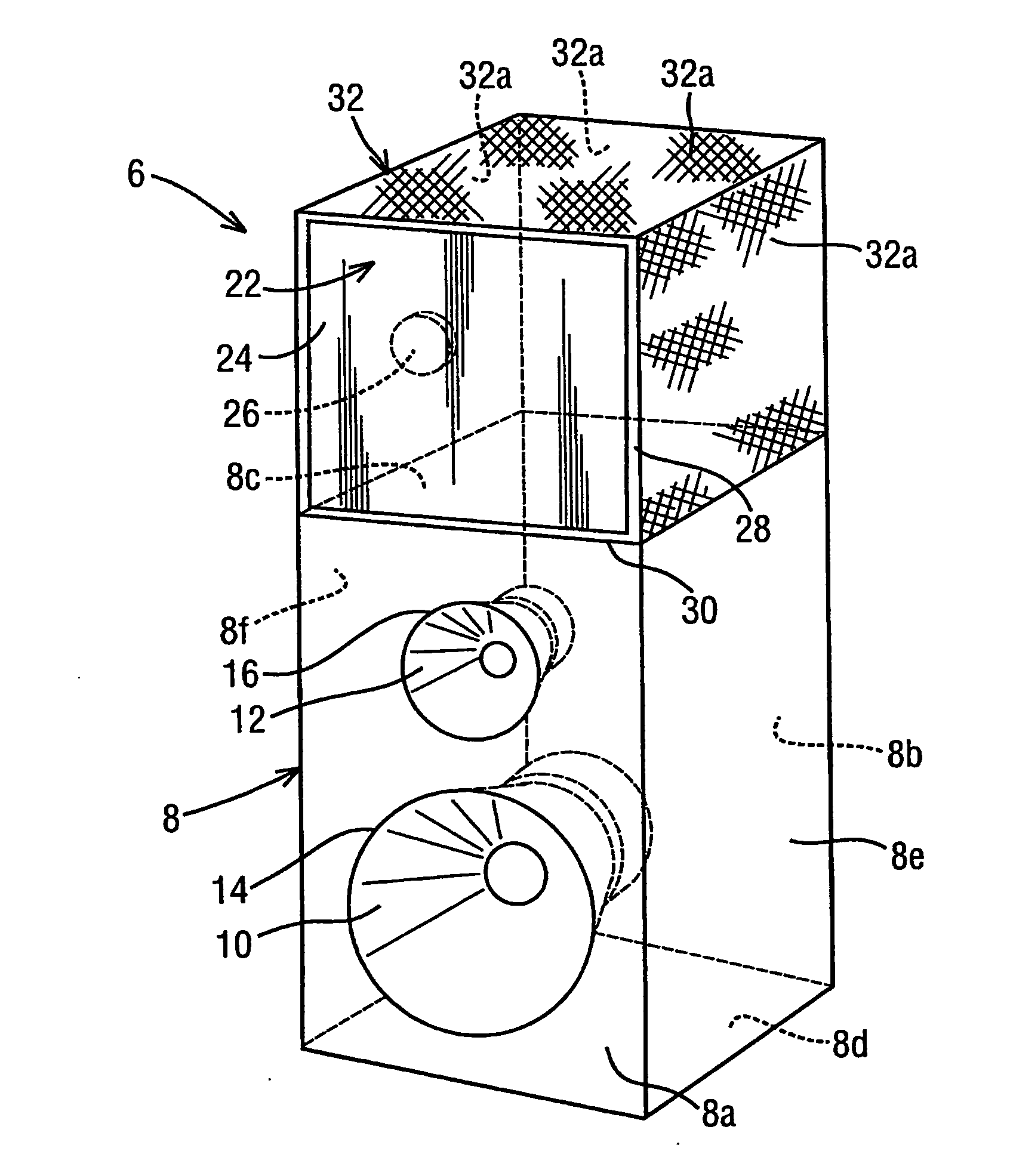
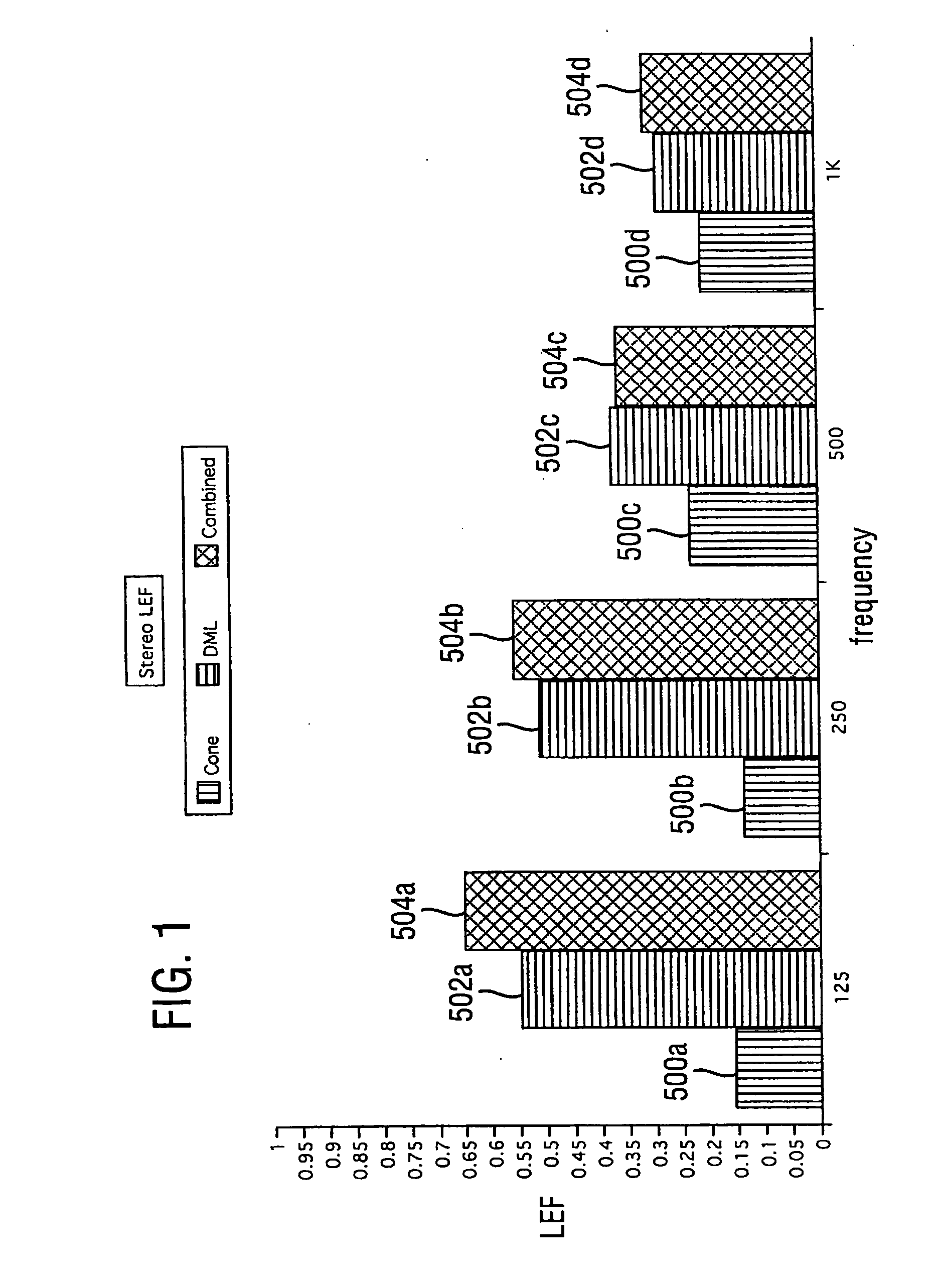
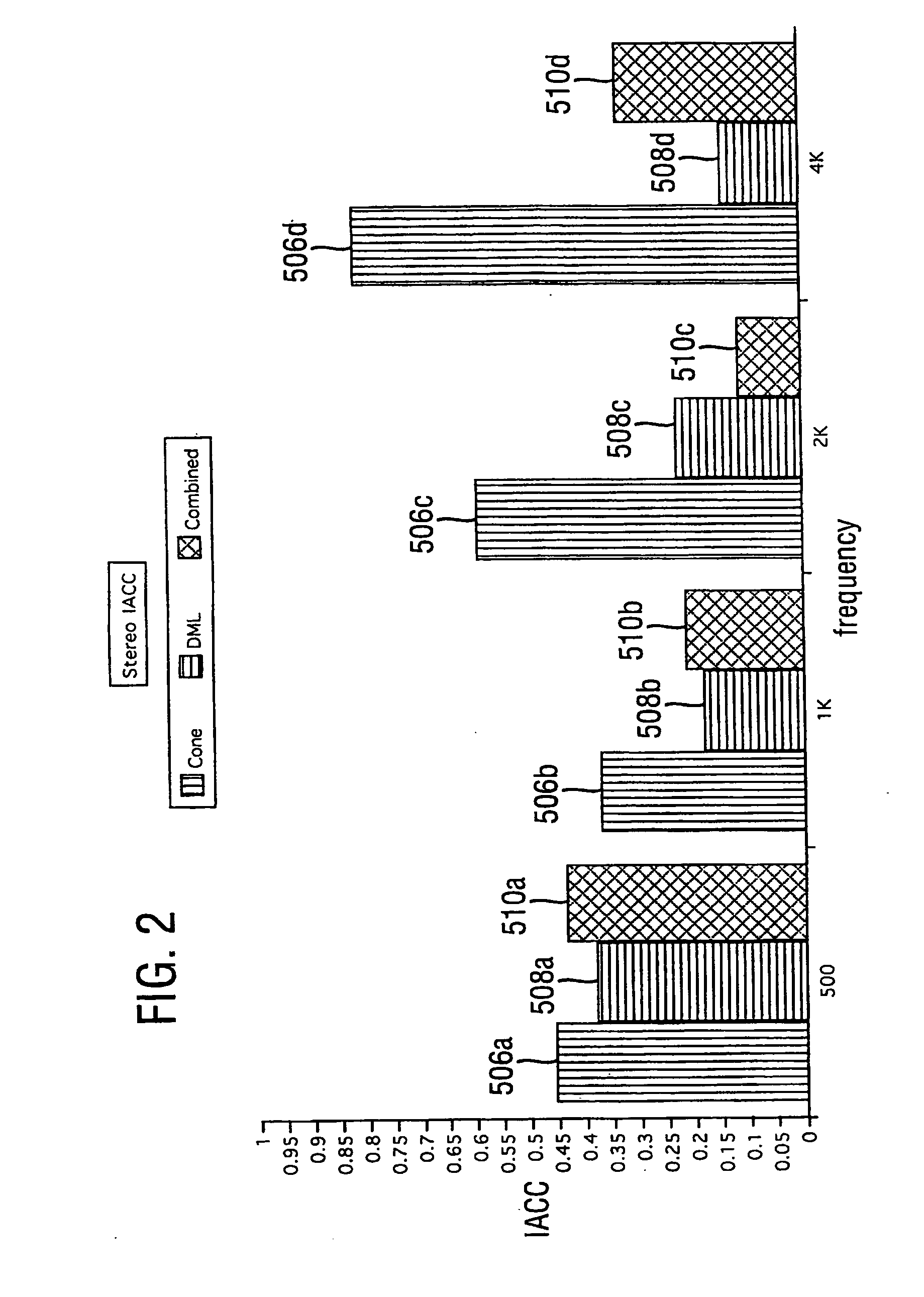
[0133] FIGS. 8 to 12 show a stereophonic sound reproduction system according to a first embodiment of the invention.
[0134] As shown in FIG. 8, the system comprises a number of input devices 2, such as a CD player, a stereo FM tuner and / or a stereo tape player; a stereophonic amplifier unit 4 of conventional construction and thus comprising the usual pre-amplifiers, control circuits and power amplifiers, and a pair of loudspeaker units 6 connected respectively to the left and right channel outputs of the amplifier 4, for reproducing stereophonic sounds such as music. The loudspeaker units 6 each include both conventional cone loudspeakers and a distributed mode loudspeaker driven in accordance with the teaching of the invention. The two loudspeaker units 6 are identical to each other.
[0135] As shown in FIG. 9, each loudspeaker unit 6 comprises a casing 8 containing a conventional full frequency range two-way cone loudspeaker system comprising a base / mid-range speaker 10 and a tweet...
second embodiment
[0145]FIG. 13 shows an alternative embodiment of the invention in which a conventional hi-fidelity music reproduction system comprising conventional input devices as previously described, a conventional stereo amplifier and a pair of conventional cone loudspeakers 50 is supplemented by a pair of auxiliary sound reproduction units 52, one for the right channel and one for the left channel, which convert the conventional hi-fidelity system to a system in accordance with the teachings of the present invention.
[0146] Each auxiliary unit 52 comprises a distributed mode loudspeaker 54 and a signal conditioning amplifier 56 having input terminals 58, connected to a respective one of the left and right loudspeaker outputs of the amplifier 4, and output terminals 60 connected to the respective distributed mode loudspeaker 54. Each signal conditioning amplifier 56 is mains powered as indicated by reference number 62. For convenience, the input terminals 58 may be connected by short lengths o...
third embodiment
[0155]FIG. 15 illustrates a modification to the input end of the circuit shown in FIG. 14 which is to permit the signal conditioning amplifier to receive input not only at high (speaker) level (as is the case in the arrangement of FIG. 14) but also at line level. For this purpose a line level input terminal 82 is provided connected to one input of an input switch 84, whose other input is connected to the output of the attenuator 64. The input detector circuit 80 is replaced by a detector circuit 86 which has two inputs, one connected to the tap 74 and the other to the line input 82. The input detector circuit 86 is arranged to send a signal to the microcontroller 76 indicating when a signal is present at line input 82 or tap 74 and the microcontroller is arranged to interpret this signal to appropriately set the input switch 84 to connect its output either to the line input or to the tap 74. As described with reference to FIG. 14, the microcontroller also causes the circuit to enter...
PUM
 Abstract
Description
Claims
Application Information
 - R&D
- Intellectual Property
- Life Sciences
- Materials
- Tech Scout
- Unparalleled Data Quality
- Higher Quality Content
- 60% Fewer Hallucinations
Browse by: Latest US Patents, China's latest patents, Technical Efficacy Thesaurus, Application Domain, Technology Topic, Popular Technical Reports.
© 2025 PatSnap. All rights reserved.Legal|Privacy policy|Modern Slavery Act Transparency Statement|Sitemap|About US| Contact US: help@patsnap.com


