
Injection forming machine

A technology of injection molding machine and driving source, applied in the field of injection molding machine, can solve the problem of uneven weight of molded products, and achieve the effect of reducing uneven weight

Inactive Publication Date: 2018-05-08
SUMITOMO HEAVY IND LTD
View PDF3 Cites 0 Cited by
  • Summary
  • Abstract
  • Description
  • Claims
  • Application Information

AI Technical Summary

Problems solved by technology

[0005] Conventionally, in the pressure holding process, the injection motor is controlled based on the detection value of the load cell, but the weight of the molded product may vary between shots.

Method used


Image

  • Injection forming machine
  • Injection forming machine

Examples


Embodiment Construction

[0020] Hereinafter, modes for implementing the present invention will be described with reference to the drawings.

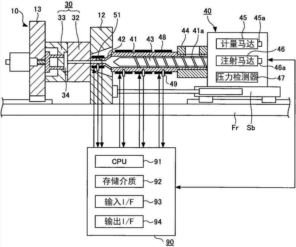
[0021] figure 1 It is a figure which shows the state at the time of mold clamping of the injection molding machine by one embodiment. Such as figure 1 As shown, the injection molding machine has a mold clamping device 10 , an injection device 40 and a control device 90 . Hereinafter, the moving direction of the screw 43 during filling ( figure 1 The middle is the left direction) as the front, and the moving direction of the screw 43 during measurement ( figure 1 The center is the right direction) and the description will be described later.

[0022] The mold clamping device 10 performs mold closing, mold clamping, and mold opening of the mold device 30 . The mold device 30 includes a fixed mold 32 and a movable mold 33 . The mold clamping device 10 has a fixed platen 12 on which a fixed mold 32 is mounted and a movable platen 13 on which a movable mold 33 ...


PUM


Abstract

The invention provides an injection forming machine which can reduce weight unevenness of formed parts through injection. The injection forming machine is provided with the components of a cylinder body which heats a forming material; a nozzle which is arranged at the front end of the cylinder body; an injection component which is configured in the cylinder body in a retreatable manner; a drivingsource which makes the injection component advance or retreat; a pressure detector which detects a pressure that is transferred between the driving source and the injection component; and a control device which controls the driving source according to the detecting result of the pressure detector, wherein the control device controls the driving source according to the detecting result of the pressure detector detected in a period from starting of a filling step to inner pressure increase of the nozzle.

Description

technical field [0001] This application claims priority based on Japanese Patent Application No. 2016-213818 filed in Japan on October 31, 2016. The entire contents of this Japanese application are incorporated herein by reference. [0002] The invention relates to an injection molding machine. Background technique [0003] Regarding the controller of the injection molding machine described in Patent Document 1, in the injection process, the servomotor for injection is controlled so that the advance speed of the screw becomes a predetermined set speed, and when the position of the screw reaches the V / P switching position At this point in time, the injection process is switched to the pressure-holding process, and in the pressure-holding process, the servomotor for injection is controlled so that the resin pressure at the front end of the screw is maintained at the pressure-holding set pressure. A load cell is used to detect the resin pressure in the packing process. [00...

Claims


Application Information

Patent Timeline
Patent Type & Authority Applications(China)
IPC IPC(8): B29C45/50B29C45/76
CPCB29C45/50B29C45/7666B29C45/77B29C2945/76006B29C2945/7618B29C2945/76381
Inventor 藤原一优
Owner SUMITOMO HEAVY IND LTD
Learn More