
A tool path optimization method for automatically generating safety cylinders for tire molds

A tire mold and tool track technology, applied in simulators, program control, instruments, etc., can solve the problems of high tool lift, inaccurate results, cumbersome process, etc., and achieve the effect of reducing the height of tool lift and solving the effect of too high tool lift

Active Publication Date: 2019-07-19
HUAZHONG UNIV OF SCI & TECH +1
View PDF5 Cites 0 Cited by
  • Summary
  • Abstract
  • Description
  • Claims
  • Application Information

AI Technical Summary

Problems solved by technology

Some foreign numerical control simulation software can establish a safe cylinder of the workpiece during the processing of the simulated workpiece, but it still cannot solve the problem of too high lifting tool in the process of tire mold processing. There are two main reasons: (1) the safety cylinder The establishment of the body is to prevent the collision between the tool and the workpiece, not to solve the problem of too high the tool; (2) the radius, center point and axis of the safety cylinder cannot be automatically identified, and these information need to be manually searched on the CAD model, because The surface features of the tire mold are complex, so the provided tire mold will be in an arbitrary coordinate system, resulting in the need to create a new plane and manually take points on the boundary of the tire mold (because the model surface is complex, take points prone to errors), etc., the process is cumbersome and the results are not accurate

Method used

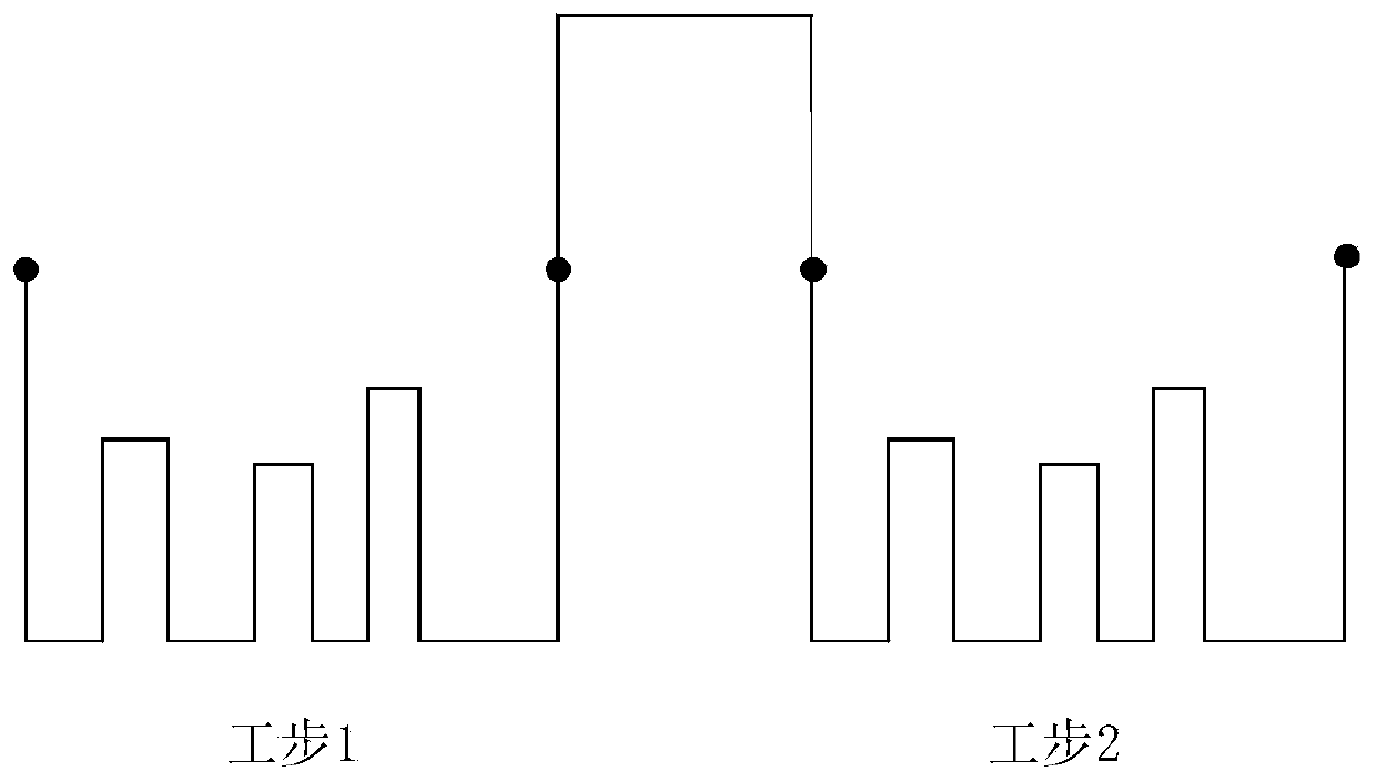
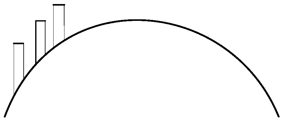
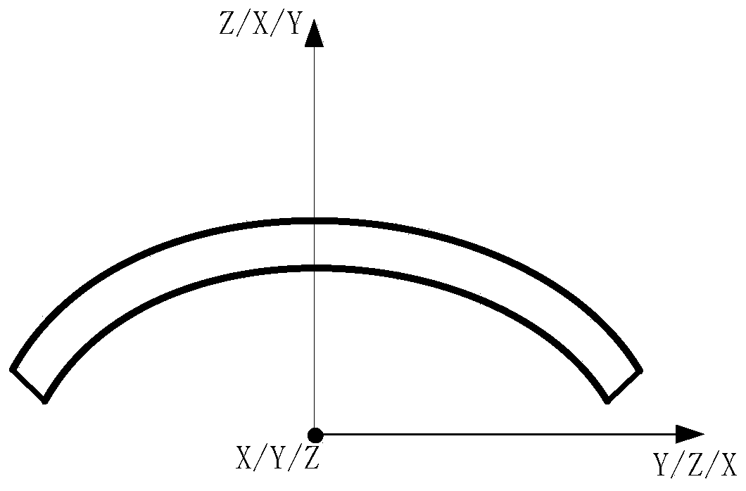

Image

  • A tool path optimization method for automatically generating safety cylinders for tire molds
  • A tool path optimization method for automatically generating safety cylinders for tire molds
  • A tool path optimization method for automatically generating safety cylinders for tire molds

Examples


Embodiment Construction

[0066] In order to make the object, technical solution and advantages of the present invention clearer, the present invention will be further described in detail below in conjunction with the accompanying drawings and embodiments. It should be understood that the specific embodiments described here are only used to explain the present invention, not to limit the present invention. In addition, the technical features involved in the various embodiments of the present invention described below can be combined with each other as long as they do not constitute a conflict with each other.

[0067] Such as figure 1 As shown, the embodiment of the present invention provides a tool path optimization method for automatically generating a tire mold safety cylinder, which includes the following steps:

[0068] (1) Triangulate the CAD model of the tire mold, that is, convert the CAD model of the tire mold into STL format (a file format of triangular grid), and then obtain the initial coo...


PUM


Abstract

The invention belongs to the field of tool path optimization, and specifically discloses a tool path optimization method for automatically generating a safety cylinder of a tire mold. The method comprises the steps of triangulating a CAD model of a tire mold, and obtaining initial coordinates of three vertices of all triangular slices on the surface of the tire mold, thus obtaining initial coordinates of N vertices in total; establishing a standard coordinate system, and converting the obtained initial coordinates of the N vertices into the standard coordinate system; establishing a target coordinate system according to the standard coordinate system and by combining characteristics of the mold; finding two arc boundaries according to the target coordinate system, and then obtaining the center of circle of the two arcs according to points on the boundaries, so as to determine the axis and radius of a safety cylinder; building a safety cylinder based on the axis and radius of the safetycylinder; and reducing the part where a cutter is lifted too high in the tool path to the surface of the safety cylinder to optimize the tool path. The method of the invention can effectively improvethe machining efficiency and ensure the machining precision, and has the advantages of convenience in operation, strong applicability and the like.

Description

technical field [0001] The invention belongs to the field of tool track optimization, and more specifically relates to a tool track optimization method for automatically generating a safety cylinder of a tire mold. Background technique [0002] Molds are an essential part of industrial production, and the processing quality of tire molds directly affects the overall performance of the car. Tire mold is the molding equipment on the tire production line, which is a very important part of automobile production. It directly affects the molding of patterns, fonts, patterns and other appearance features on the tire, and also affects the overall performance of the automobile. [0003] At present, many enterprises mainly use multi-axis CNC machining in the production of tire molds. In the multi-axis CNC machining of tire molds, the tool path generated by CAM software generally has the problem of too high tool lift. There are two main reasons for the problem of too high lift in tir...

Claims


Application Information

Patent Timeline
Patent Type & Authority Patents(China)
IPC IPC(8): G05B19/4097
CPCG05B19/4097G05B2219/36252
Inventor 李振瀚黄璐璐李喜艳闵康江海清何姗姗
Owner HUAZHONG UNIV OF SCI & TECH
Learn More