
Waveform optimization method of mimo radar based on iterative optimization network

A radar waveform, iterative optimization technology, applied in the radar field, can solve the problems of insensitivity, deep learning waveform design cannot converge initial value, etc., achieve excellent performance, superior performance, and solve the effect of invalid iteration

Active Publication Date: 2022-07-01
YANGTZE DELTA REGION INST (QUZHOU) UNIV OF ELECTRONIC SCI & TECH OF CHINA
View PDF6 Cites 0 Cited by
  • Summary
  • Abstract
  • Description
  • Claims
  • Application Information

AI Technical Summary

Problems solved by technology

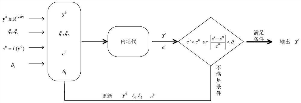
[0006] The technical problem to be solved by the present invention is: the weighted time delay of the correlation only optimizes the WISL of the waveform and the deep learning waveform design cannot converge and the initial value is not sensitive. The present invention provides a MIMO radar waveform based on an iterative optimization network to solve the above problems Optimization

Method used


Image

  • Waveform optimization method of mimo radar based on iterative optimization network
  • Waveform optimization method of mimo radar based on iterative optimization network
  • Waveform optimization method of mimo radar based on iterative optimization network

Examples


Embodiment 1

[0111] MIMO radar consists of M antennas, each of which transmits N sub-pulse waveforms. In order to ensure the efficient use of energy, the signal is defined as a constant modulus, then each sub-pulse can be expressed as:

[0112]

[0113] where m=1,...,M, n=1,...,N. and need to guarantee y m (n) ∈ [0, 2π]. definition As the sequence of waveforms transmitted by the mth antenna. The formula (1) represents the nth sub-pulse signal transmitted by the mth antenna. Therefore, all sub-pulse waveform sets transmitted by all antennas can be represented as a matrix Since there are M signals, each of which transmits N sub-pulses, there are N rows and M columns in total. Each column represents the waveform emitted by an antenna, and each element represents a sub-pulse. Similarly, the phase matrix corresponding to the signal matrix can be expressed as

[0114] The orthogonality of waveforms is often determined by autocorrelation and cross-correlation. where the waveform ...

Embodiment 2

[0219] The two methods of the present invention are compared with the existing scheme "Document "H. He, P. Stoica, and J. Li, "Designing unimodular sequence sets with good correlations; including an application to MIMO radar," IEEE Trans.Signal Process., vol .57, no.11, pp.4391–4405, Nov. 2009, "the scheme published", the existing scheme two "document "Cui G, Yu X, Piezzo M, et al. Constant modulus sequenceset design with good correlation properties[ J].Signal Processing, 2017, 139:75-85. "Published Scheme" for comparison.

[0220] In this embodiment, the convergence factor θ of the outer iteration 1 =0.001, default input phase y 0 is a random normalized phase sequence. Convergence factor θ for inner iteration 2 =0.001, the maximum number of iterations of the inner loop N max = 5000, the minimum number of iterations N min =1000, the convergence interval is E=100, the default weight vector is l 1 =l 2 =l 3 =l 4 =l 5 =1. The learning rate of the Adam deep learning alg...


PUM


Abstract

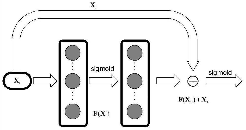
The invention discloses a MIMO radar waveform optimization method based on an iterative optimization network, relates to the technical field of radar, and solves the problems that the weighted delay of the correlation only optimizes the WISL of the waveform, and the deep learning waveform design cannot converge and the initial value is insensitive. The invention includes inputting a normalized random vector or an optimized normalized phase vector in the set network model, and outputting a signal matrix, which is a MIMO radar waveform; and setting the signal processing function as the loss function of the network model , the signal processing function is used to drive the network model, and the parameters of the network model are optimized by the Adam deep learning method. The present invention promotes more thorough optimization and also solves the problem of invalid iterations.

Description

technical field [0001] The invention relates to the technical field of radar, in particular to a MIMO radar waveform optimization method based on an iterative optimization network. Background technique [0002] Because MIMO radar has better performance than phased array radar, MIMO radar waveform has good autocorrelation and cross-correlation characteristics, which has received extensive attention, and has more advantages than traditional radar. On the one hand, when a waveform with good correlation is transmitted, the MIMO radar can effectively suppress noise and interference, thereby improving the signal-to-interference-noise ratio. MIMO radar has significant advantages in target positioning, parameter estimation and improving spatial resolution, and the virtual aperture can be increased by filter at the receiving end. At present, the waveform optimization of MIMO radar is mainly based on phase waveform design. [0003] MIMO radar waveforms are designed with correlation-...

Claims


Application Information

Patent Timeline
Patent Type & Authority Patents(China)
IPC IPC(8): G01S13/02G01S7/02G06N3/04G06N3/08
CPCG01S13/02G01S7/02G06N3/08G06N3/045
Inventor 王鹏飞魏志勇胡进峰张伟见李玉枝邹欣颖董重
Owner YANGTZE DELTA REGION INST (QUZHOU) UNIV OF ELECTRONIC SCI & TECH OF CHINA
Learn More