
Method and device for achieving bullet time shooting effect and panoramic camera

A shooting effect, panoramic camera technology, applied in the field of image processing, can solve the problems of inaccurate control, high shooting cost, slow shooting progress, etc.

Active Publication Date: 2018-05-15
ARASHI VISION INC
View PDF6 Cites 9 Cited by
  • Summary
  • Abstract
  • Description
  • Claims
  • Application Information

AI Technical Summary

Problems solved by technology

[0003] The object of the present invention is to provide a method, device, computer-readable storage medium and panoramic camera for realizing the shooting effect of bullet time. Need, and the price is expensive, the problem of high shooting cost

Method used


Image

  • Method and device for achieving bullet time shooting effect and panoramic camera
  • Method and device for achieving bullet time shooting effect and panoramic camera
  • Method and device for achieving bullet time shooting effect and panoramic camera

Examples


Embodiment 1

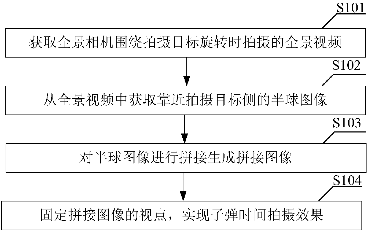
[0023] see figure 1 The method for achieving the bullet time shooting effect provided by Embodiment 1 of the present invention includes the following steps: It should be noted that if there are substantially the same results, the method for realizing the bullet time shooting effect of the present invention does not depend on figure 1 The flow sequence shown is limited.

[0024] S101. Acquire a panoramic video shot when the panoramic camera rotates around the shooting target.

[0025] In Embodiment 1 of the present invention, when the shooting target is the photographer, the panoramic video shot when the panoramic camera rotates around the shooting target can be specifically shot in the following manner:

[0026] The photographer shakes the auxiliary line or the selfie stick connected to the panoramic camera above the head, so that the panoramic camera rotates around the photographer, and at the same time, the motion state of objects and / or people located on the side of the ph...

Embodiment 2

[0040] see figure 2 The device for realizing the bullet time shooting effect provided by Embodiment 2 of the present invention includes:

[0041] The panoramic video acquisition module 11 is used to obtain the panoramic video taken when the panoramic camera rotates around the shooting target;

[0042] The hemispherical image acquisition module 12 is used to acquire the hemispherical image near the shooting target side from the panoramic video;

[0043] Stitching module 13, for splicing hemispherical images to generate spliced ​​images;

[0044] The viewpoint fixing module 14 is used to fix the viewpoint of the spliced ​​images to realize the shooting effect of bullet time.

[0045] The device for achieving the bullet-time shooting effect provided by the second embodiment of the present invention and the method for realizing the bullet-time shooting effect provided by the first embodiment of the present invention belong to the same idea, and its specific implementation proce...

Embodiment 3

[0047] Embodiment 3 of the present invention provides a computer-readable storage medium. The computer-readable storage medium stores a computer program. When the computer program is executed by a processor, the bullet-time shooting effect as provided in Embodiment 1 of the present invention is realized. steps of the method.


PUM


Abstract

The invention belongs to the field of image processing, and provides a method and a device for achieving the bullet time shooting effect and a panoramic camera. The method comprises the steps of acquiring a panoramic video shot when the panoramic camera rotates around a shooting target; acquiring hemispherical images close to the shooting target from the panoramic video; splicing the hemisphericalimages to generate a spliced image; fixing the viewpoint of the spliced image, and achieving the bullet time shooting effect. According to the invention, the bullet time shooting effect can be shot by only one panoramic camera, so that the shooting cost of the bullet time shooting effect is low. Meanwhile, the bullet time shooting effect is obtained through the panoramic video shot when the panoramic camera rotates around the shooting target. Therefore, the precision is high.

Description

technical field [0001] The invention belongs to the field of image processing, and in particular relates to a method, a device and a panoramic camera for realizing the shooting effect of bullet time. Background technique [0002] Bullet time (Bullet time) is used in movies, TV commercials or computer games, using computer-aided photography technology to simulate variable speed effects, such as enhanced slow motion, time still and other effects. The bullet time shooting effect was originally achieved with a series of still cameras (rather than video cameras) surrounding the subject. These camera arrays are typically shuttered simultaneously or sequentially. Combining each frame of photos taken by each camera can create a perspective rotation effect on a still object, or a super slow motion effect. Theoretically, a virtual camera can achieve an infinite viewing angle and frame refresh rate, but the implementation with a still camera is usually limited by the shooting path. ...

Claims


Application Information

Patent Timeline
Patent Type & Authority Applications(China)
IPC IPC(8): G06T3/40G06T3/00
CPCG06T3/4038G06T3/06H04N5/2627H04N23/698H04N23/683H04N23/682H04N23/684H04N23/6842H04N23/6845
Inventor 陈聪姜文杰刘靖康
Owner ARASHI VISION INC
Learn More