Grinding device capable of collecting liquid and achieving locking

A grinding device and stop technology, applied in grinding devices, grinding machine tools, grinding/polishing equipment, etc., can solve the problems such as the inability to remove and recycle the grinding waste liquid in time, affecting the grinding and assembly accuracy of the valve seat, and the inability to fix it. To achieve the effect of simple structure, good grinding effect and precise grinding

CN108044499AInactive Publication Date: 2018-05-18成都元始信息科技有限公司
0 Cites 0 Cited by

Patent Information

Authority / Receiving Office
CN · China
Patent Type
Applications(China)
Current Assignee / Owner
Publication Date
2018-05-18
Estimated Expiration
Not applicable · inactive patent

Smart Images

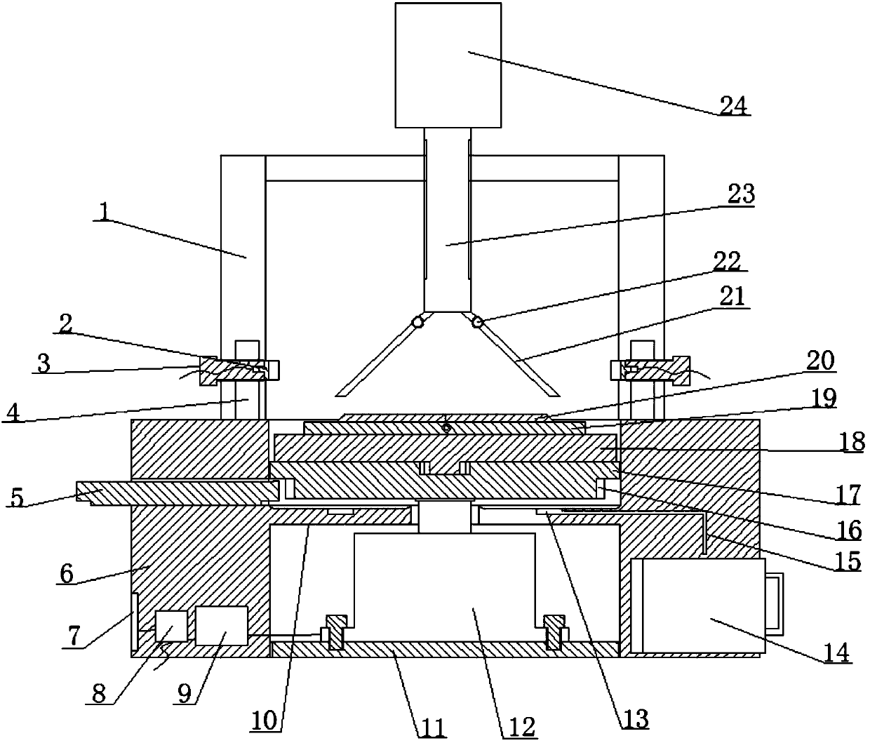
  • Figure 1
    Figure 1
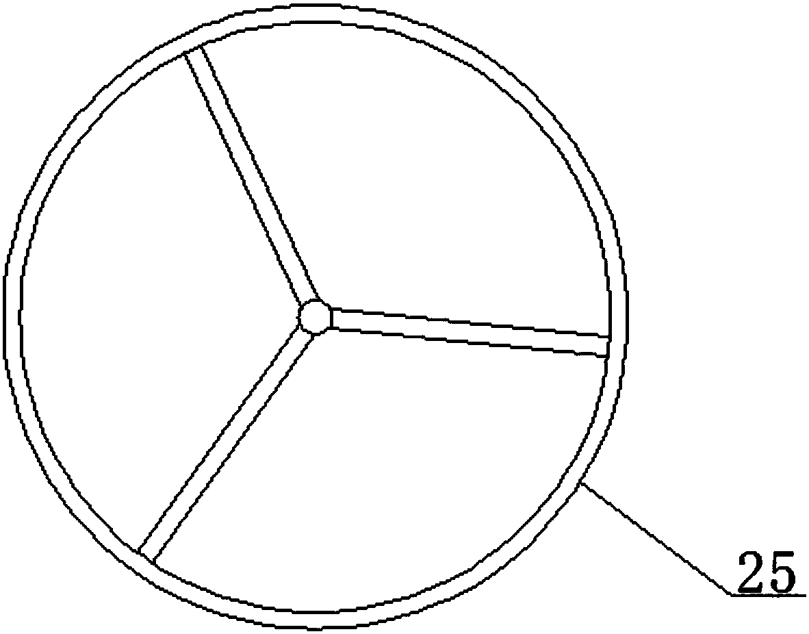
  • Figure 2
    Figure 2
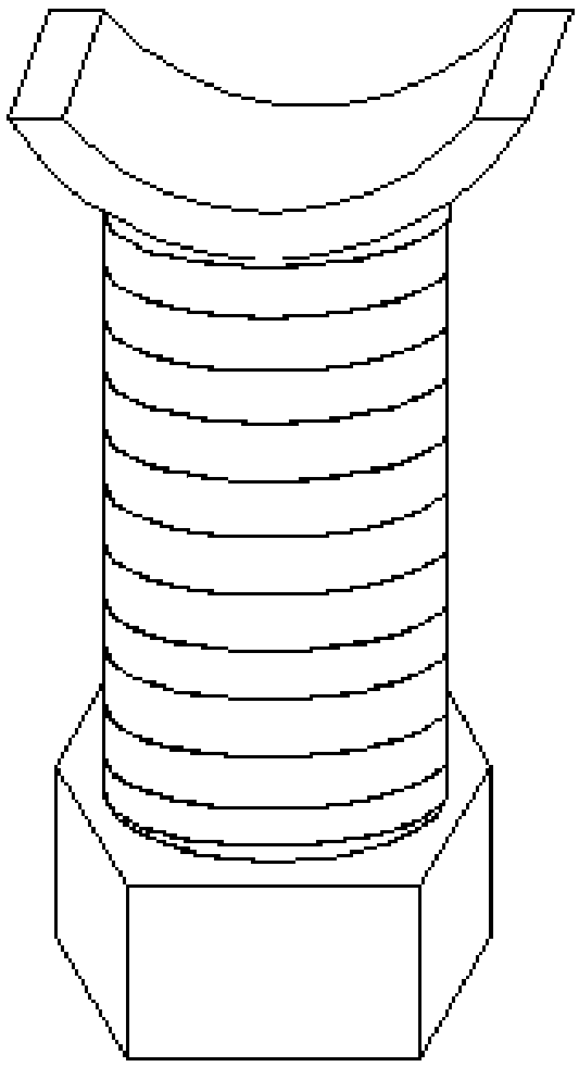
  • Figure 3
    Figure 3
Patent Text Reader

Abstract

The invention relates to a grinding device capable of collecting liquid and achieving locking. The device comprises a base, a mounting cavity is formed in the middle of the base, the middle of the mounting cavity is isolated by an isolation ring to form an upper cavity and a lower cavity, the lower end of the lower cavity is in threaded connection with the base through a bottom plate to seal the lower cavity, the upper end of the bottom plate is fixedly provided with a rotation motor through a fixing screw, a rotating shaft of the rotation motor is vertically arranged, two clamping devices aresymmetrically arranged t the positions, on the two sides of the upper cavity, of the upper end face of the base, the upper cavity is sequentially provided with a rotation tray and a fixed plate frombottom to top, an end face grinding round table is arranged in the middle of the upper end of the fixed plate, an inclined face grinding round table is arranged at the upper end of the end face grinding round table, and the rotating shaft is fixedly connected with the lower end of the rotation tray. the device is simple in structure and small in size, one person can operate multiple grinding devices for simultaneous grinding, the cost and energy consumption are low, a valve base can be stably clamped, during grinding, it is ensured that the valve base can achieve uniform-speed grinding, grinding is more accurate, grinding effect is good, and the precision is high.
Need to check novelty before this filing date? Find Prior Art

Description

technical field

[0001] The invention relates to a grinding device, which belongs to the technical field of mechanical processing. More specifically, the invention relates to a grinding device capable of collecting liquid and stopping. Background technique

[0002] Valves are pipeline accessories used to open and close pipelines, control flow direction, adjust and control the parameters (temperature, pressure and flow) of the conveying medium. According to their functions, they can be divided into shut-off valves, check valves, and regulating valves. The valve is a control component in the fluid delivery system, which has functions such as cut-off, adjustment, flow diversion, reverse flow prevention, pressure stabilization, flow diversion or overflow pressure relief.

[0003] Valves generally include a valve body, a sealing cover, a valve seat, a valve core (disc) and a valve stem, which constitute a fluid-tight structure as a whole. Among them, the valve seat is a removable ...

Examples

Embodiment Construction

[0027] The present invention will be further described below in conjunction with the accompanying drawings. Embodiments of the present invention include, but are not limited to, the following examples.

[0028] Such as Figure 1-Figure 4 A grinding device that can collect liquid and stop shown includes a base 6, and the middle part of the base 6 is provided with an installation cavity, and the middle part of the installation cavity is separated by an isolation ring 10 to form an upper chamber and a lower chamber, and the lower chamber The lower end is threadedly connected with the base 6 through the base plate 11 to seal the lower chamber. The upper end of the base plate 11 is fixed with a rotating motor 12 by fixing screws, and the rotating shaft of the rotating motor 12 is vertically arranged.

[0029] The upper end surface of the base 6 is located on both sides of the upper chamber and is symmetrically provided with two clamping devices. The clamping device includes a posi...