Connecting structure and method for prefabricated columns and prefabricated beams of fabricated building frame structure

A technology of frame structure and connection structure, which is applied in the direction of building structure and construction, can solve the problems of inconvenient production, high stiffness of node area, complicated structure, etc., and achieve the effect of improving construction efficiency, reasonable disassembly and assembly.

Active Publication Date: 2018-05-18
SICHUAN UNIV
View PDF7 Cites 12 Cited by
  • Summary
  • Abstract
  • Description
  • Claims
  • Application Information

AI Technical Summary

Problems solved by technology

[0021] The purpose of the present invention is to overcome the deficiencies of the prior art. The purpose is to provide a prefabricated column and prefabricated beam connection structure and method for the prefabricated building frame structure, which solves the need for secondary pouring of concrete in the prior art; the structure is complex and inconvenient to manufacture; Too large, the ductility is poor; the joint surface is prone to stress concentration and local failure

Method used


Image

  • Connecting structure and method for prefabricated columns and prefabricated beams of fabricated building frame structure
  • Connecting structure and method for prefabricated columns and prefabricated beams of fabricated building frame structure
  • Connecting structure and method for prefabricated columns and prefabricated beams of fabricated building frame structure

Examples


Embodiment 1

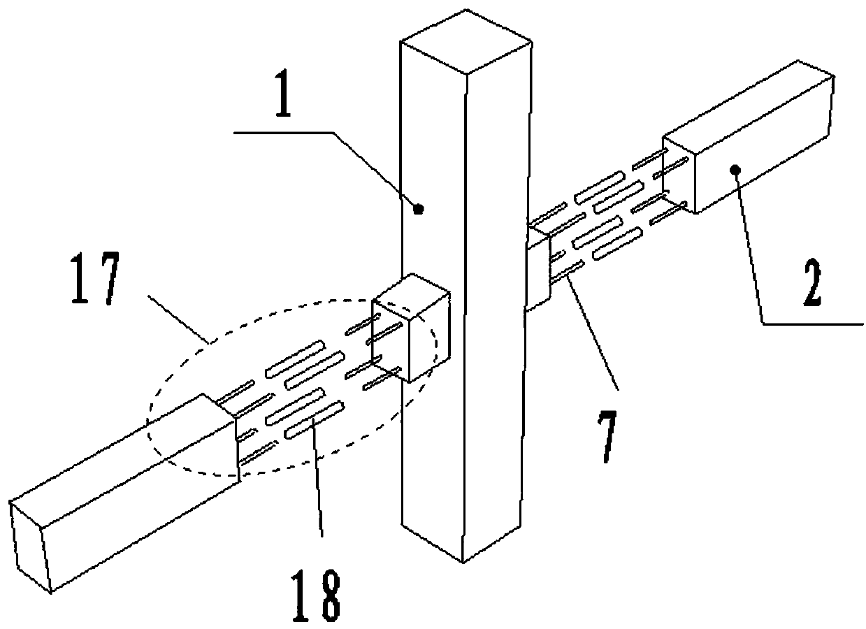
[0076] Such as Figure 4-22 As shown, the prefabricated column and prefabricated beam connection structure of a prefabricated building frame structure of the present invention includes a prefabricated column 1 and a prefabricated beam 2, the prefabricated column 1 and the prefabricated beam 2 are formed by pouring reinforced concrete, and the prefabricated column 1 is surrounded by a There is at least one concealed corbel section 3, and the prefabricated column 1 and the concealed corbel section 3 are integrally poured, such as Figure 6-8 Shown, on the prefabricated column 1, it is the prefabricated central column that surrounds four pieces of hidden corbel sections 3, which are arranged on the frame (such as Figure 10 In the middle of the shown), the prefabricated side columns surrounded by three hidden corbel sections 3 on the prefabricated column 1 are set on the frame (such as Figure 10 As shown), the prefabricated corner columns surrounded by two hidden corbel section...

Embodiment 2

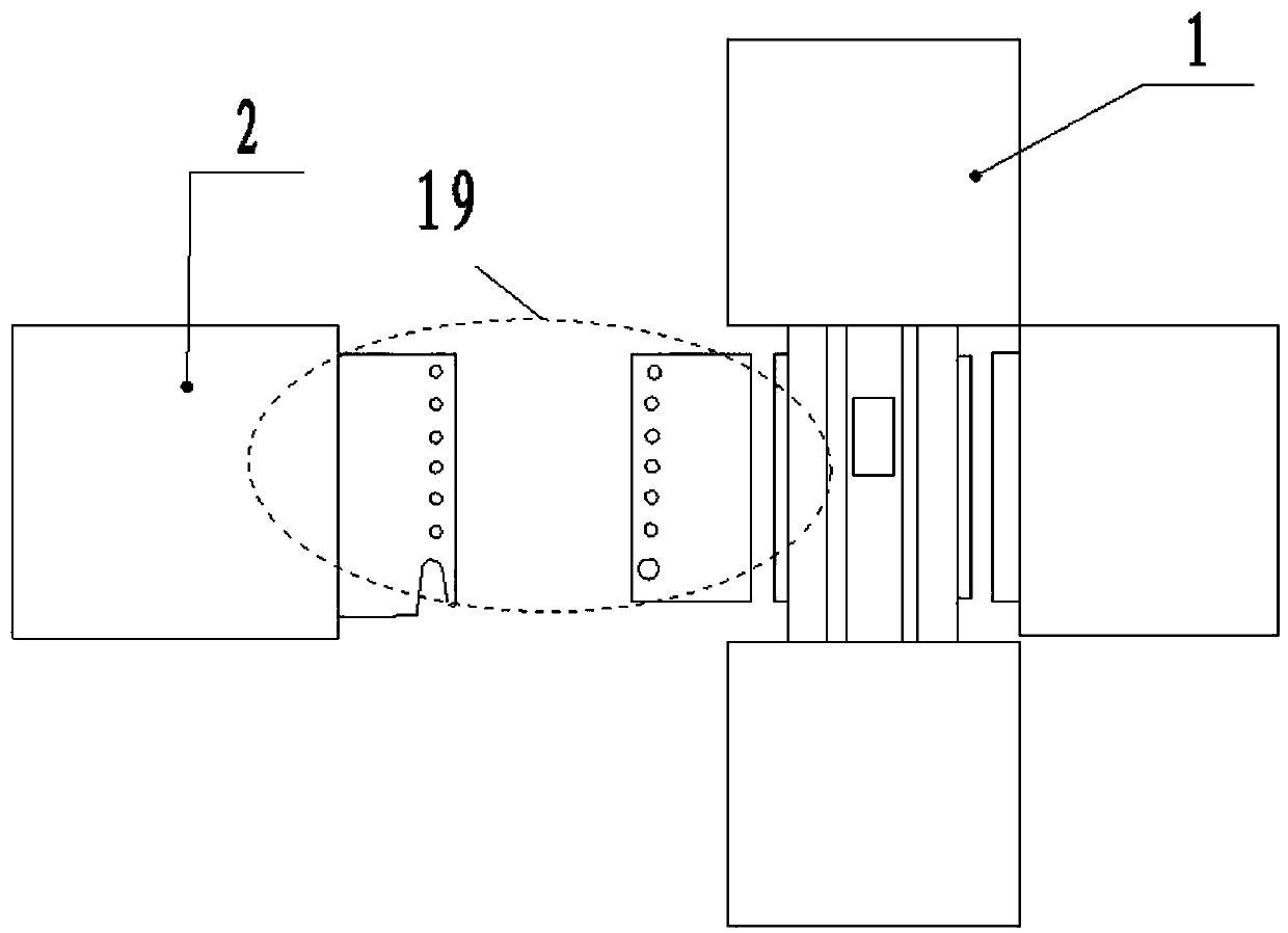
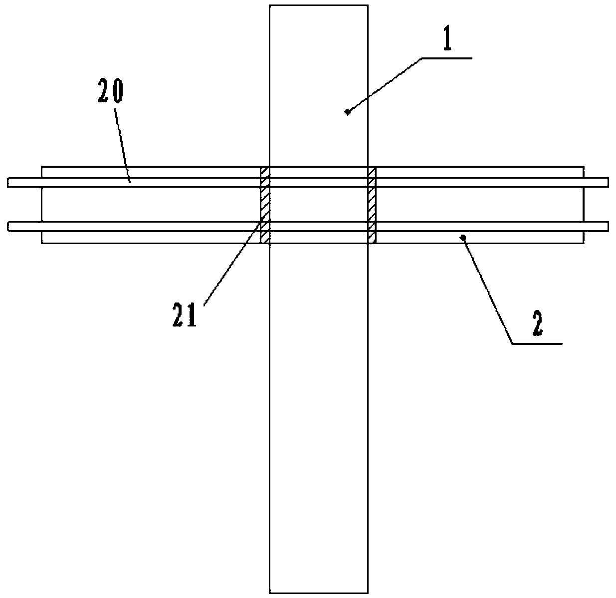
[0086] Such as Figure 4-22As shown, the present invention is a prefabricated column and prefabricated beam connection structure of a prefabricated building frame structure. The prefabricated column 1 is pre-embedded with prefabricated column reinforcing ribs 22, and at least one end of the prefabricated column 1 is provided with a prefabricated column. The column steel plate 23, the prefabricated column steel plate 23 is connected with the prefabricated column reinforcing rib 22, and the ring surface of the prefabricated column steel plate 23 is evenly provided with connecting through holes 24, and the prefabricated column 1 corresponding to the connecting through hole 24 is preset with The installation groove 25 is connected by bolts. When two prefabricated columns 1 need to be connected, after the prefabricated column steel plates 23 at the ends of the two prefabricated columns 1 are butted, the bolts 26 are installed in the connecting through holes 24 to realize the connect...

Embodiment 3

[0088] Such as Figure 4-22 Shown, the present invention a kind of prefabricated column and prefabricated beam connection method of prefabricated building frame structure, it comprises steps:

[0089] In the prefabricated component factory, the prefabricated component consisting of the prefabricated column 1 and the concealed corbel section 3 is poured as a whole, and the prefabricated column 1 and the concealed corbel section 3 are integrally poured;

[0090] Pouring the prefabricated beam 2; the prefabricated beam 2 is connected to the prefabricated beam lap joint 5 of the hidden corbel section 3 on the two prefabricated columns 1 through the corbel section lap joints 8 at both ends, and the corbel section lap joints 8 are lapped with the prefabricated beam After the joint 5 is lapped, connect the corbel connection steel plate 9 on the corbel section lap joint 8 with the prefabricated beam connection steel plate 6 on the prefabricated beam lap joint 5 .

[0091] The pouring...


PUM


Abstract

The invention discloses a connecting structure and method for prefabricated columns and prefabricated beams of a fabricated building frame structure. The connecting structure comprises the prefabricated columns and the prefabricated beams. At least one hidden bracket section is arranged on each prefabricated column in an embracing mode, and each hidden bracket section is internally provided with abracket longitudinal reinforcing rib. A prefabricated beam lap joint is arranged at the outer end of each hidden bracket section, and prefabricated beam connecting steel plates are pre-buried in theupper end faces and the lower end faces of the prefabricated beam lap joints correspondingly. The prefabricated beam connecting steel plates and the bracket longitudinal reinforcing ribs are connected. Prefabricated beam longitudinal reinforcing ribs are arranged in the prefabricated beams, and the two ends of the prefabricated beams are provided with bracket section lap joints matched with the prefabricated beam lap joints correspondingly. Bracket connecting steel plates are pre-buried in the upper end faces and the lower end faces of the bracket section lap joints correspondingly. The bracket connecting steel plates are connected with the prefabricated beam longitudinal reinforcing ribs. Each prefabricated beam is connected to the prefabricated beam lap joints of the hidden bracket sections on the two corresponding prefabricated columns in a lap-joint mode correspondingly, and the bracket connecting steel plates on the bracket section lap joints and the prefabricated beam connectingsteel plates on the prefabricated beam lap joints are connected.

Description

technical field [0001] The invention relates to the technical field of construction engineering, in particular to a connection structure and method for prefabricated columns and prefabricated beams of prefabricated building frame structures. Background technique [0002] The construction industry is a pillar industry that drives my country's economic development. According to the statistics of the Ministry of Housing and Urban-Rural Development: Since 2009, the proportion of the added value of the construction industry to the GDP has always remained above 6.5%. In recent years, the state has strategically determined to promote the development of construction industrialization, and has issued a series of policy documents. [0003] At present, the level of construction industrialization in developed countries in the world is relatively high. For example, the construction industrialization of European and American countries reaches 75%, Sweden is as high as 80%, and Japan can r...

Claims


Application Information

Patent Timeline
Patent Type & Authority Applications(China)
IPC IPC(8): E04B1/21
Inventor 陈江熊峰段瑞峰
Owner SICHUAN UNIV
Why Eureka
Try Eureka