

No gap centering and limit compression pitch circle fixture
A pitch circle and fixture technology, applied in positioning devices, clamping, manufacturing tools, etc., can solve the problem of small clamping force and achieve the effect of convenient loading and unloading
Active Publication Date: 2019-10-01
WENLING MINGHUA GEAR
View PDF6 Cites 0 Cited by
- Summary
- Abstract
- Description
- Claims
- Application Information
AI Technical Summary
Problems solved by technology
The purpose of the present invention is to provide a gapless centering and position limiting clamping pitch circle fixture, which separates positioning and clamping, avoids deformation caused by excessive clamping force, and also solves vibration caused by small clamping force , thus fundamentally solving the processing problem of such parts
Method used
View moreImage
Smart ImageViewing Examples

Examples
Embodiment Construction
Login to View More PUM
 Abstract
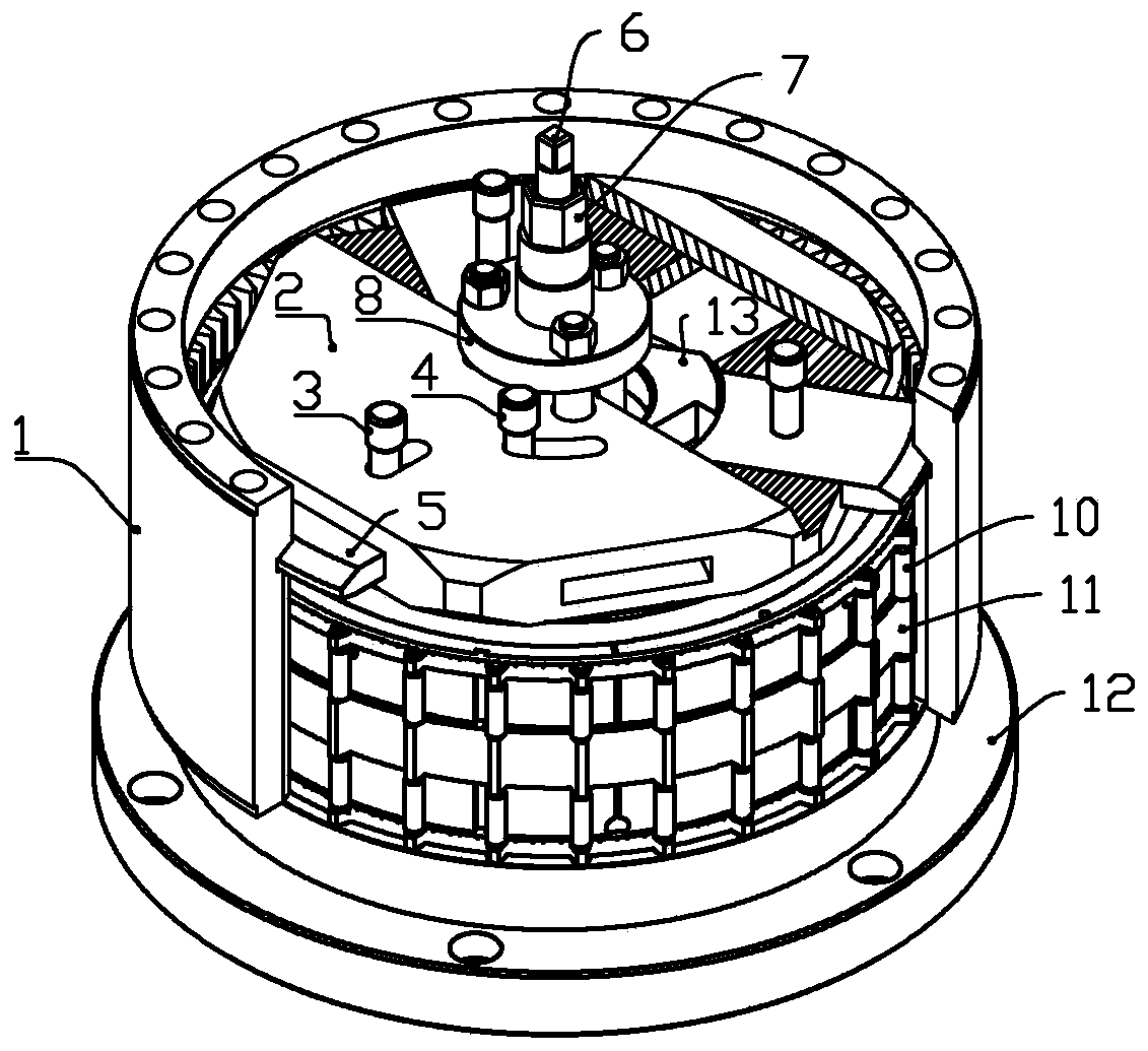
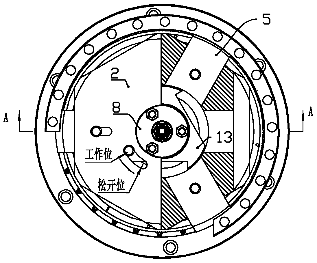
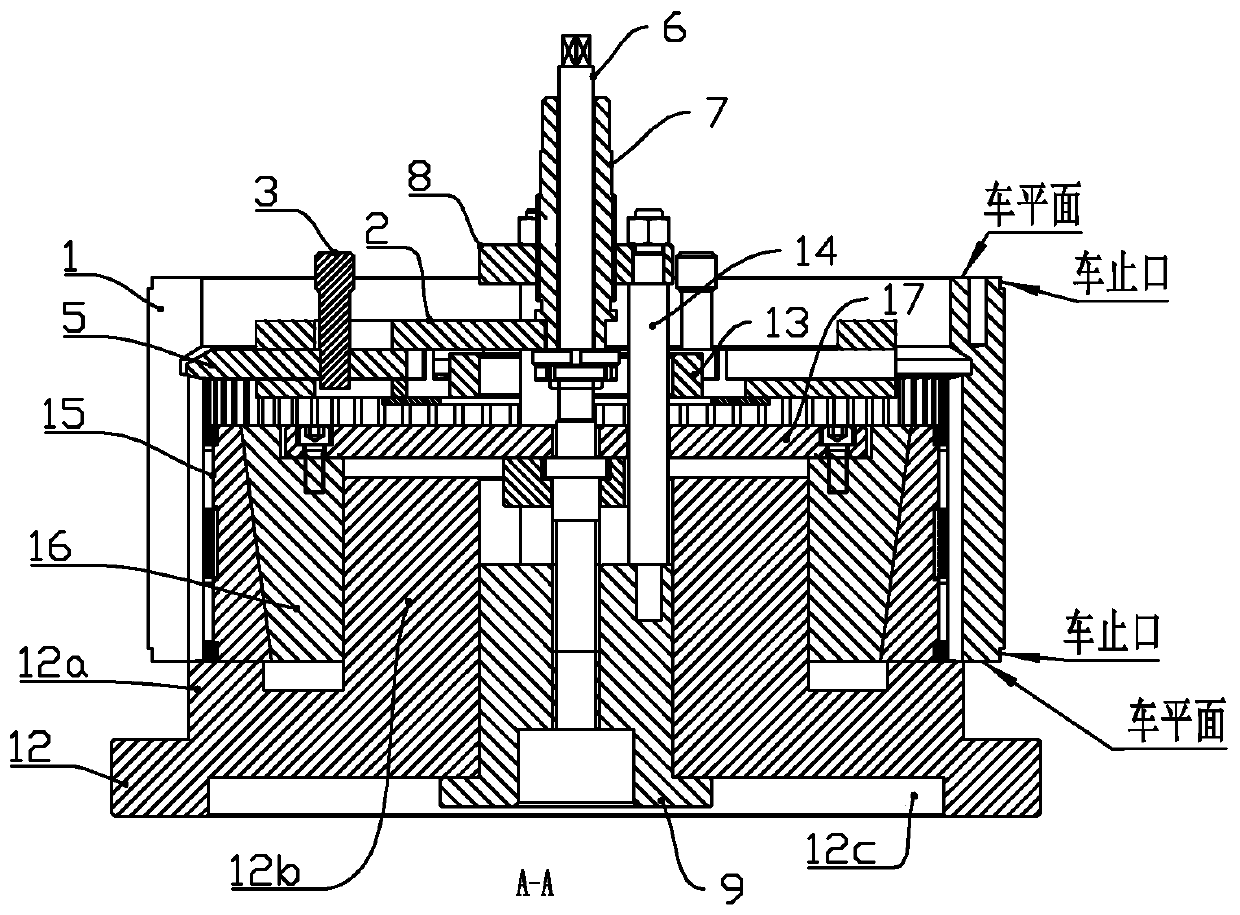
A gapless centering and limit compressing pitch circle clamp comprises a base. The base comprises a cylindrical boss arranged in the middle and a supporting boss arranged around the cylindrical boss,a through hole is formed in the cylindrical boss, the hole bottom of the through hole is matched with a nut lining, and a radial positioning mechanism and an axial compressing mechanism are arranged on the base. According to the gapless centering and limit compressing pitch circle clamp, positioning and clamping are separately conducted, deformation caused by overlarge clamping force is avoided, vibration caused by the small clamping force is also avoided, and thus the machining problem of parts of the type is fundamentally solved.
Description
technical field The invention belongs to the technical field of ring gear clamps, in particular to a gapless centering and position limiting compression pitch circle clamp. Background technique With the application of large-scale wind power generation equipment, there is an important part: the ring gear. Because of the requirements of the working environment, the ring gear is often thin-walled in order to reduce the weight as much as possible in the design. For the processing of such large thin-walled ring gear parts, if the teeth of the ring gear are through, it is more convenient to process, especially for the case where the tooth shape of the ring gear is not through (see Figure 9 teeth lock up). Because of this situation, the end face of the ring gear has to be machined and there is no place to be compressed, and the problem of clamping deformation will occur when the pitch circle is used for centering and clamping. Because, the ring gear will inevitably produce a cer...
Claims
Login to View More Application Information
Patent Timeline
 Patent Type & Authority Patents(China)
IPC IPC(8): B23Q3/06
Inventor 戴捷戴忠楼颜忠辉
Owner WENLING MINGHUA GEAR