Fastening sand tooling and turbine casing casting system

A turbine shell and sand mold technology, which is applied to casting molding equipment, cores, molds, etc., can solve the problems of sand mold cracking and leaking molten iron, turbine shell sand mold cracking, and leaking molten iron, etc., to solve cracking, ensure casting quality, Simple to use effects

Active Publication Date: 2020-02-11
CRRC CHANGZHOU AUTO PARTS CO LTD +1
View PDF6 Cites 0 Cited by
  • Summary
  • Abstract
  • Description
  • Claims
  • Application Information

AI Technical Summary

Problems solved by technology

[0004] The purpose of the present invention is to provide a fastening tool for sand molds, which can solve the problem of cracking and leakage of molten iron in sand molds during pouring
[0005] Another object of the present invention is to provide a turbine casing casting system, which includes the above fastening sand mold tooling, which can solve the problem of cracking and leakage of molten iron in the turbine casing sand mold during pouring

Method used


Image

  • Fastening sand tooling and turbine casing casting system
  • Fastening sand tooling and turbine casing casting system
  • Fastening sand tooling and turbine casing casting system

Examples


Embodiment 1

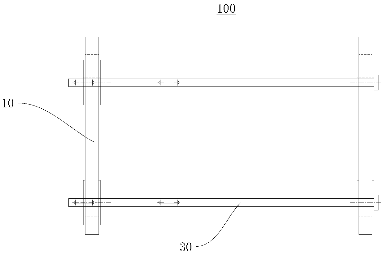
[0040] Please refer to figure 1 , the present embodiment provides a sand mold fastening tool 100, including a pressing frame 10, a connecting rod 30 and a fixing pin.

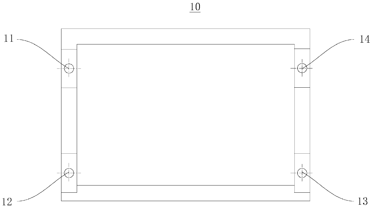
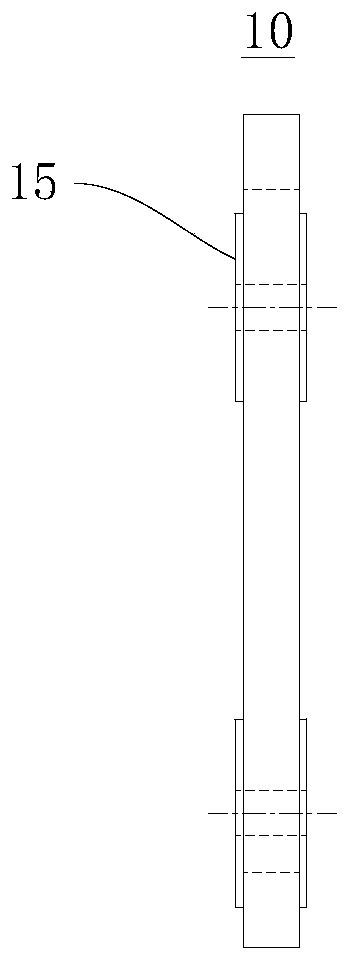
[0041] Specifically, please combine Figure 2 to Figure 7 . The pressing frame 10 is used to be arranged on both sides of the sand mold in the horizontal direction, and the pressing frame 10 has at least two connection holes and is respectively located on opposite sides of the pressing frame 10 .

[0042] The connecting rod 30 includes a limiting end 31 and a rod body 33 , the limiting end 31 is disposed at one end of the rod body 33 , and the rod body 33 has a pin hole. When press-fitting the sand mold, the connecting rod 30 is passed through the connection holes of the compression frame 10 on both sides of the sand mold, the limit end 31 is located on the side of one of the compression frames 10 away from the sand mold, and the pin hole is located on the other side of the compression frame 10. On the side ...

Embodiment 2

[0073] This embodiment provides a turbine casing casting system, including a turbine casing sand mold 101 and the fastening sand mold tooling 100 in Embodiment 1.

[0074] The fastening sand mold tooling 100 clamps and fixes the turbine casing sand mold 101 in the horizontal direction. The sizes of the used pressing frames 10 , connecting rods 30 and fixing pins are determined according to the turbine casing sand mold 101 .

[0075] like Figure 8 As shown, the fastening sand mold tooling 100 can also press-fit three turbine shell sand molds 101 at the same time, which is more conducive to increasing the output for the manufacture of the same type of turbine shell.

[0076] By adopting the fastening sand mold tooling 100 in Embodiment 1, the turbine casing casting system can perform the casting work of the turbine casing with quality and quantity, improve the casting quality and efficiency, and benefit the production efficiency of the enterprise.

[0077] In summary, the fas...


PUM


Abstract

The invention provides a sand mold fastening tool and a turbine shell casting system, and relates to the technical field of casting. The sand mold fastening tool comprises pressing frames, a connecting rod and a fixed pin. The pressing frames are used for arranging on two sides of the horizontal direction of a sand mold, and are provided with connecting holes on two opposite sides thereof. The connecting rod comprises a limiting end and a rod body; the limiting end is arranged at one end of the rod body; and the rod body is provided with a pin hole. When the sand mold is pressed, the connecting rod penetrates through the connecting holes of the pressing frames on two sides of the sand mold; the limiting end is positioned on the side, far from the sand mold, of one pressing frame; the pin hole is positioned on the side, far from the sand mold, of the other pressing frame; and the fixed pin is mounted in the pin hole to enable the pressing frames on two sides of the sand mold to satisfymutual approaching tendency. The turbine shell casting system comprises a turbine shell sand mold and the sand mold fastening tool. The sand mold fastening tool and the turbine shell casting system can effectively solve the problem of leakage of molten iron in the casting process of several turbine shells with special structures needing horizontal box distribution and vertical pouring.

Description

technical field [0001] The invention relates to the field of casting technology, in particular to a fastening sand mold tooling and a turbine casing casting system. Background technique [0002] With the vigorous development of the automobile industry, the turbocharger industry has also developed by leaps and bounds. Due to the different shapes and processes of the volute and exhaust pipe products, the process is also different. For the shell-making process using coated sand, the sand mold needs to be compacted before pouring to prevent the sand mold from cracking during the pouring process. [0003] For some conventional volutes, only horizontal boxing and horizontal pouring are required, and the upper mold is pressed by pressing iron, but for some special-structure turbine shells, horizontal boxing and vertical pouring are required, which is prone to leakage of molten iron Problem arises. Contents of the invention [0004] The object of the present invention is to prov...

Claims


Application Information

Patent Timeline
Patent Type & Authority Patents(China)
IPC IPC(8): B22C9/22B22C9/02
Inventor 吴翩翩郑立林梁万波段文恒
Owner CRRC CHANGZHOU AUTO PARTS CO LTD
Why Eureka
Try Eureka