
Self-release upper pulley for rope connection

A technology of rope connection and pulleys, applied in the field of self-release upper pulleys, which can solve the problems of laborious adjustment

Inactive Publication Date: 2018-05-22
黄丽贤
View PDF6 Cites 0 Cited by
  • Summary
  • Abstract
  • Description
  • Claims
  • Application Information

AI Technical Summary

Problems solved by technology

However, since the upper door and window frame is located at a higher position, it is very laborious to adjust

Method used


Image

  • Self-release upper pulley for rope connection
  • Self-release upper pulley for rope connection
  • Self-release upper pulley for rope connection

Examples


Embodiment a1

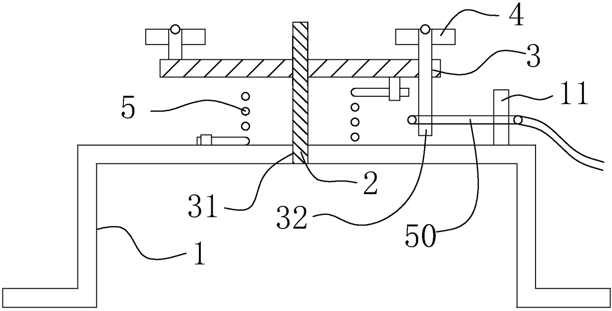
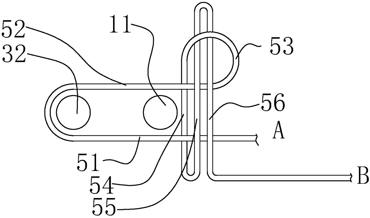
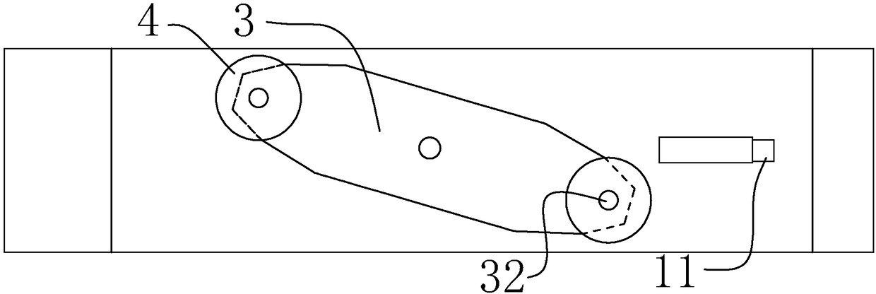
[0018] refer to Figure 1 to Figure 3 , which is embodiment a1 of the present invention, specifically:

[0019] A self-releasing upper pulley connected by a rope, including a base frame 1 arranged in the left and right directions, and a rope 50, the base frame 1 is provided with a vertically arranged rotating shaft 2, the base frame 1 is fixedly connected with the rotating shaft 2, and rotates The plate 3 is provided with a shaft hole 31, the shaft hole 31 is connected with the rotating shaft 2, and the base frame 1 is connected with the rotating plate 3 with an expansion spring 5, so that the rotating plate 3 has a tendency to rotate around the rotating shaft 2, and the two ends of the rotating plate 3 Roller 4 is provided, and rotating shaft 2 is located between the two ends of rotating plate 3, and rotating plate 3 is connected with control shaft 32, and base frame 1 is provided with fixed rod 11, and rope 50 encloses a fixed ring to connect fixed rod 11. 1. The control sh...

Embodiment a2

[0024] refer to Figure 4 , which is embodiment a2 of the present invention, specifically:

[0025] The knot in this embodiment adopts a dead knot, and the rope 50 is a plastic rope, and the electric heating sleeve 6 is sleeved on the rope 50, and the rope is fused by heating, so that the automatic release of the rotating plate can be realized.


PUM


Abstract

The invention discloses a self-release upper pulley for rope connection. The self-release upper pulley comprises a base frame, and further comprises a rope, wherein a rotary shaft is arranged on the base frame; the base frame is fixedly connected with the rotary shaft; a shaft hole is formed in a rotary plate; the shaft hole is connected with the rotary shaft; the base frame is connected with therotary plate through an unfolding spring; the two ends of the rotary plate are equipped with roller wheels; a control shaft is connected on the rotary plate; a fixed rod is arranged on the base frame;and the rope is enclosed into a fixed ring for enclosing the fixed rod and the control shaft together and forming a rope knot, so that the rotary plate is prevented from being changed into a releasestate from a put-away state. The self-release upper pulley is mounted on an upper door-window frame, and the front-rear distance between the two roller wheels is small, so that a door window can be conveniently pushed into the guide rail slot; the fixed rod and the control shaft can be released by cutting of the rope through a tool or releasing the rope knot, so that the rotary plate is in a release state, and therefore, the rotary plate can be driven by the unfolded spring to rotate around the rotary shaft; and the roller wheels abut against the vertical wall of the guide rail slot, so that the looped distance between the two rollers is great. The self-release upper pulley is used for door and window fittings.

Description

technical field [0001] The invention relates to the field of door and window accessories, in particular to a rope-connected self-release upper pulley. Background technique [0002] Existing doors and windows slide in the guide rail groove, and upper pulleys need to be set on the upper door and window frame. In order to adapt to guide rail grooves of different widths, the upper pulley includes a base frame, and a rotating plate is arranged on the base frame. There are two rollers, and the angle between the base frame and the rotating plate is adjusted through a rigid mechanical adjustment structure, so as to control the distance of the two rollers protruding out of the base frame, so that it can adapt to guide rail grooves of different widths. However, since the upper door and window frame is located at a higher position, it is very laborious to adjust. Contents of the invention [0003] The technical problem to be solved by the present invention is to provide an upper pul...

Claims


Application Information

Patent Timeline
Patent Type & Authority Applications(China)
IPC IPC(8): E05D13/00
CPCE05D13/00
Inventor 黄丽贤
Owner 黄丽贤
Learn More