Spring travel limiter for overrunning alternator decoupler

a technology of alternator decoupler and travel limiter, which is applied in the direction of mechanical actuated clutches, couplings, slip couplings, etc., can solve the problems of engine vibration, reduced component durability, and inacceptable noise and vibration levels, and achieve the effect of preventing rotational movemen

Active Publication Date: 2010-05-11
LITENS AUTOMOTIVE INC
View PDF60 Cites 139 Cited by
  • Summary
  • Abstract
  • Description
  • Claims
  • Application Information

AI Technical Summary

Benefits of technology

[0009]The carrier includes first and second sides and an anti-ramp up boss projecting from one of the sides. A torsion spring extends between the hub and carrier for transferring torque therebetween. A thrust plate is fixedly mounted on the second end of the hub and has a slot formed therein extending between first and second ends for receiving the anti-ramp up boss. The anti-ramp up boss travels within the slot between the first and second ends for limiting rotation between the carrier and the thrust plate while selectively preventing rotational movement of the torsion spring relative to the hub and carrier.

Problems solved by technology

Internal combustion engines operate as a pulse system, constantly accelerating and decelerating and causing engine vibrations.
This can result in unacceptable levels of noise and vibration along with reduced component durability due to high fluctuating loads and vibrations.
Additionally, rapid engine accelerations and decelerations, such as during transmission shifts and engine startup or shutdown, cause belt squeal from slippage between the belt and the pulley, as well as heavy impact loading on the belt.

Method used


Image

  • Spring travel limiter for overrunning alternator decoupler
  • Spring travel limiter for overrunning alternator decoupler
  • Spring travel limiter for overrunning alternator decoupler

Examples


Embodiment Construction

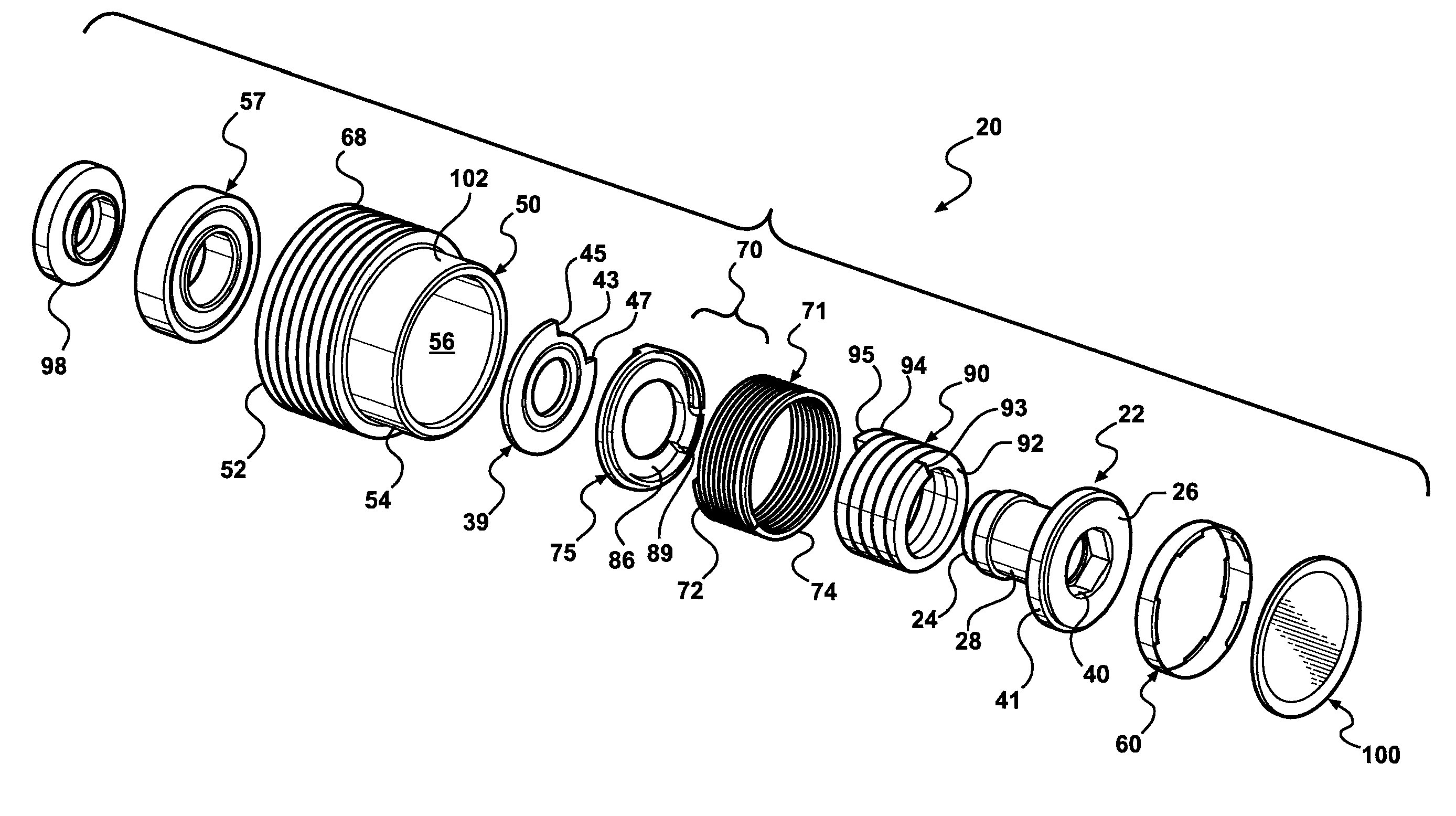
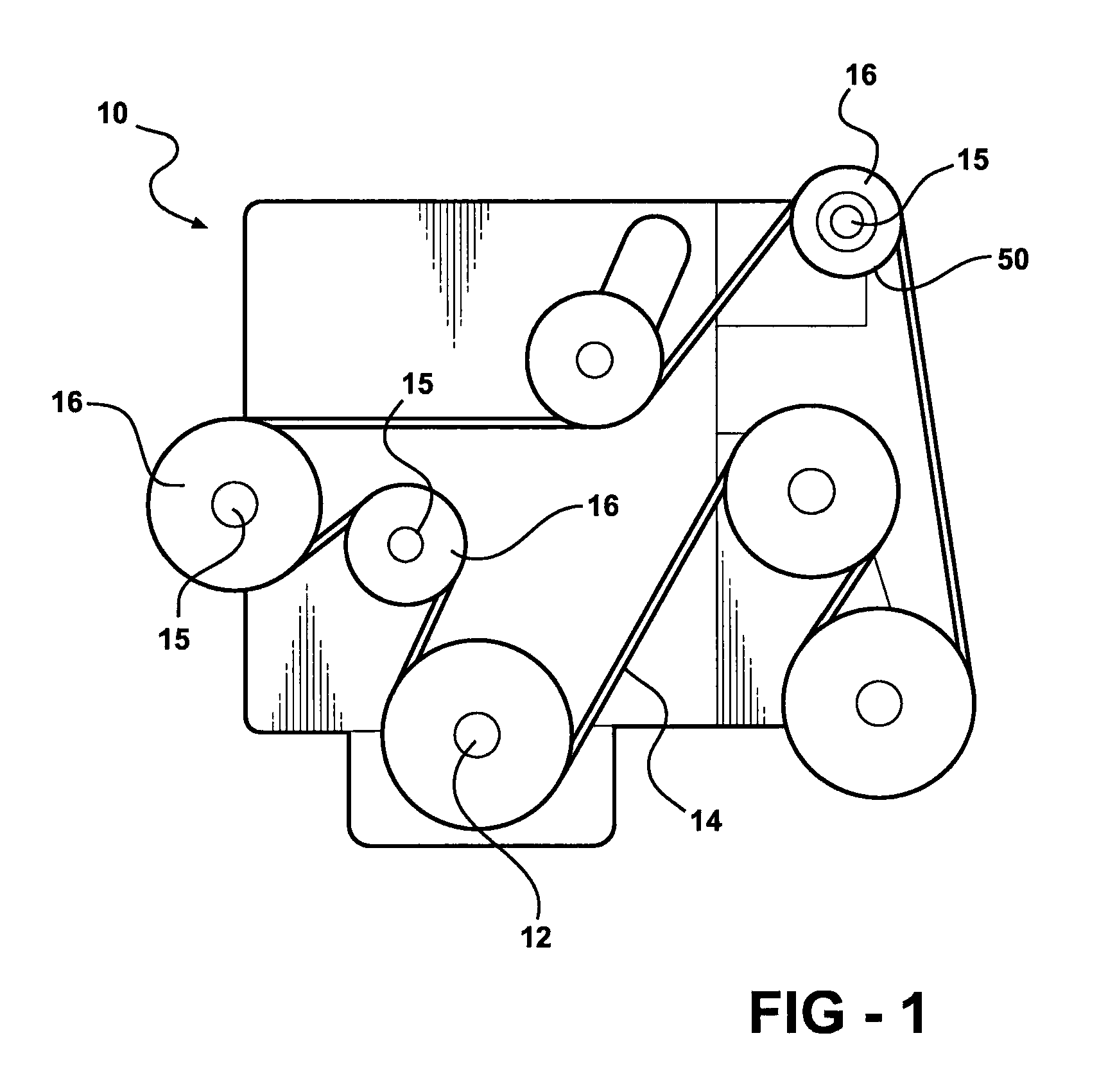
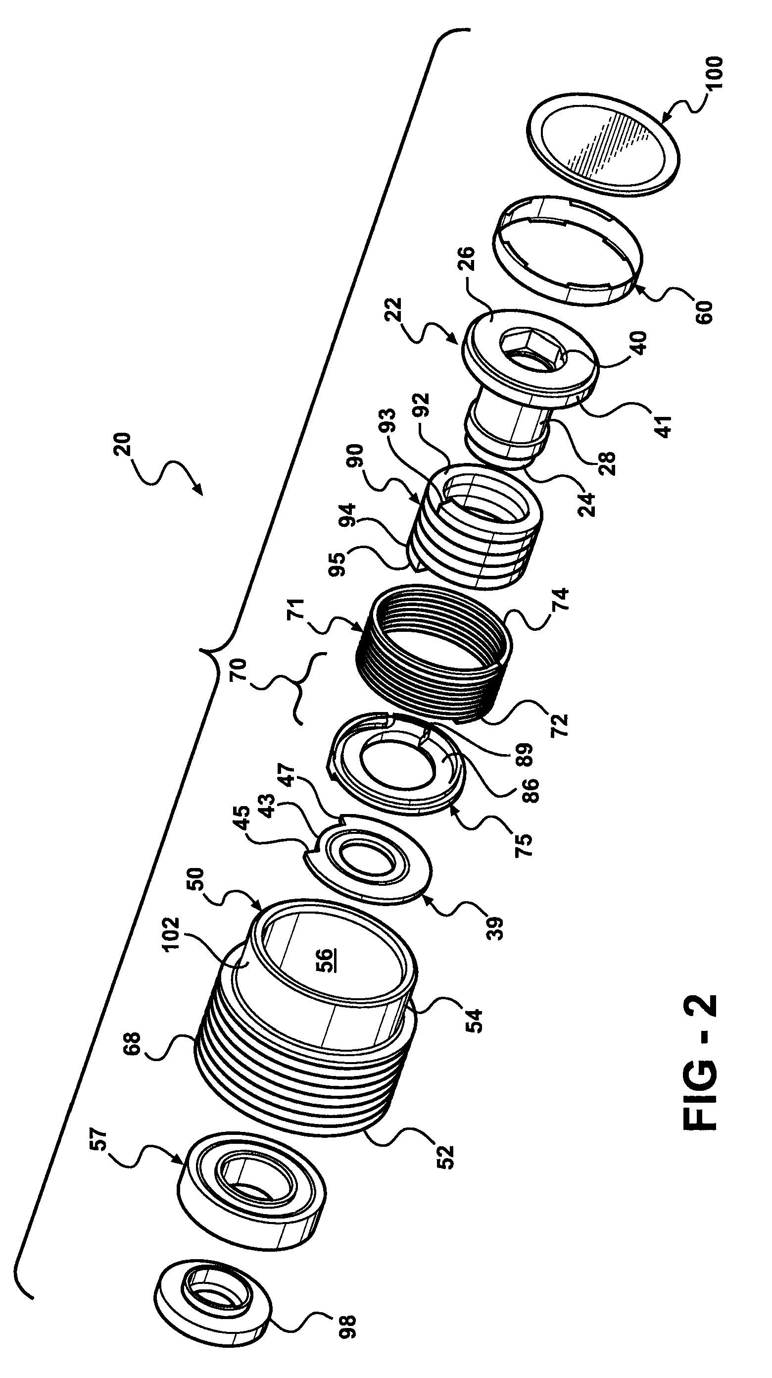
[0025]Referring to FIG. 1, an engine for an automotive vehicle is generally indicated at 10. The engine 10 includes a crankshaft 12 driving an endless serpentine belt 14, as commonly known by those having ordinary skill in the art. The engine 10 also includes a plurality of belt driven accessory components 16, such as an alternator, compressor, etc., mounted to a drive shaft 15 and driven by the belt 14. A pulley 50 is operatively coupled to each of the belt driven accessory components 16 for driving the components 16 via rotation of the pulley 50. Described in greater detail below and shown in FIG. 2, a decoupler assembly 20 is operatively assembled between the belt 14 and any one or more of the belt driven accessory components 16 for automatically decoupling the component 16 from the belt 14 when the belt 14 decelerates relative to the component 16 and allowing the speed of the belt 14 to oscillate relative to the belt driven accessory component 16. Additionally, a detailed descri...


PUM


Abstract

A decoupler assembly for transferring rotary movement between an engine driven shaft and a serpentine belt. The decoupler includes a hub configured to be assembled to the shaft. The hub has a helical first slot formed therein. A pulley is rotatably coupled to the hub. A carrier is mounted on the hub and includes a helical second slot formed therein, as well as an anti-ramp up boss formed thereon. A thrust plate is fixed to the hub and has a slot formed therein. A torsion spring is compressed between a hub end retained in the helical first slot and a carrier end retained in the helical second slot for transferring torque between the hub and carrier. The anti-ramp up boss travels within the slot formed in the thrust plate for limiting rotation between the carrier and thrust plate and preventing rotation of the torsion spring relative to the hub and carrier.

Description

CROSS-REFERENCE TO RELATED APPLICATIONS[0001]This application is a national phase entry of International Patent Application PCT / CA2004 / 002094 filed Dec. 9, 2004, which claims priority to U.S. Provisional Patent Application No. 60 / 528,225 filed Dec. 9, 2003.FIELD OF THE INVENTION[0002]The invention relates to a drive shaft and belt driven component of an automotive vehicle, and more particularly, to a decoupler assembly for the allowing the belt driven component to operate temporarily at a speed different than that of the drive shaft and to decouple or mechanically isolate the driven component from the drive shaft and reduce torsional vibrations therebetween.BACKGROUND OF THE INVENTION[0003]It is widely known in an automotive vehicle engine to transfer a portion of the engine output to a plurality of belt driven accessory components utilizing an endless serpentine belt. Typically, each component includes a pulley drivingly engaged with the belt and the belt is driven by an output pul...

Claims


Application Information

Patent Timeline
Patent Type & Authority Patents(United States)
IPC IPC(8): F16D23/00F16D7/02F16D41/20
CPCF16D3/52F16D7/022F16D41/206E05Y2800/22Y10S474/902E05Y2201/49F16D3/72F16D3/12F16D7/00F16D7/02F16D41/00
Inventor JANSEN, CHRISTIANANTCHAK, JOHN R.
Owner LITENS AUTOMOTIVE INC
Why Eureka
Try Eureka