
Pilates Machine Tension Device Support System

a technology of tension device and support system, which is applied in the direction of resistance force resistor, gymnastic exercise, sport apparatus, etc., can solve the problems of reducing the peacefulness of exercise, the tension spring is fully exposed to the user, and the exercise machine is not as aesthetically pleasing to the user or others, so as to increase or decrease the tension applied

Active Publication Date: 2014-05-01
LAGREE TECH INC
View PDF5 Cites 148 Cited by
  • Summary
  • Abstract
  • Description
  • Claims
  • Application Information

AI Technical Summary

Benefits of technology

This invention is about a Pilates exercise machine that has a frame and a platform that moves on top of the frame. The machine has a tension assembly that allows the platform to be selectively tensioned in a certain direction. This tension is provided by a plurality of pulleys and tension devices that are attached between the frame and the platform. The tension members can be engaged or disengaged to change the level of tension. The invention allows for adjustable tension to provide varying levels of workouts for the user. Its technical effect is its ability to provide a customizable and effective workout for the Pilates client.

Problems solved by technology

The main problem with conventional tension spring systems utilized on Pilates machines is that when the user moves the platform away from the end of the machine where the tension springs are connected, the tension springs are fully exposed to the user while they perform their exercise.
When the tension springs are exposed during operation, the exercise machine is not as aesthetically pleasing to the user or others.
Furthermore, there is a risk that the user may accidentally engage the tension springs resulting in an injury.
Also, when the movable platform is extended away from the end of the exercise machine, the tension springs are exposed and noise from the springs is free to be emitted without obstruction thereby reducing the peacefulness of the exercise.

Method used


Image

  • Pilates Machine Tension Device Support System
  • Pilates Machine Tension Device Support System
  • Pilates Machine Tension Device Support System

Examples


Embodiment Construction

A. Overview

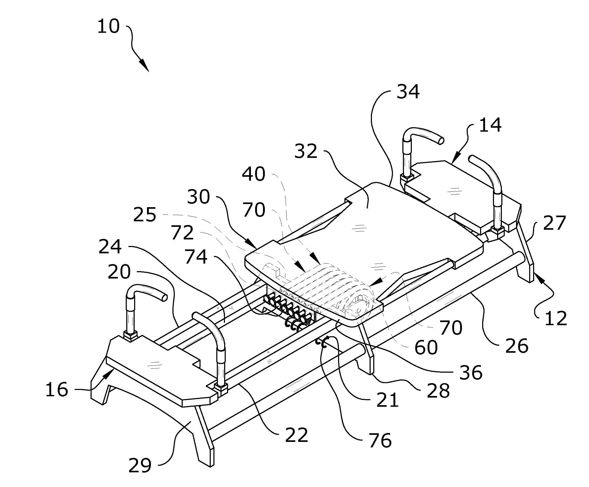
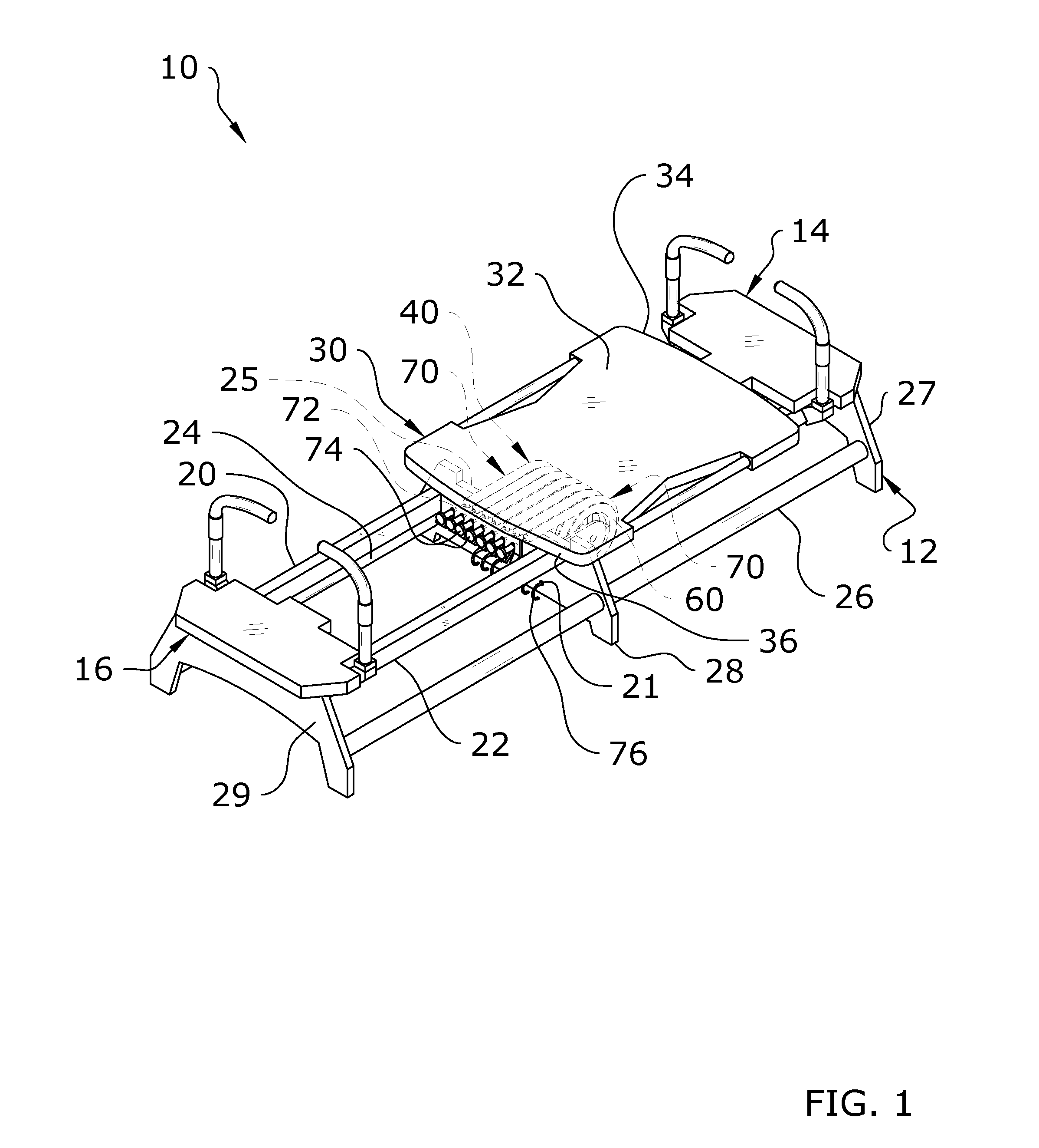
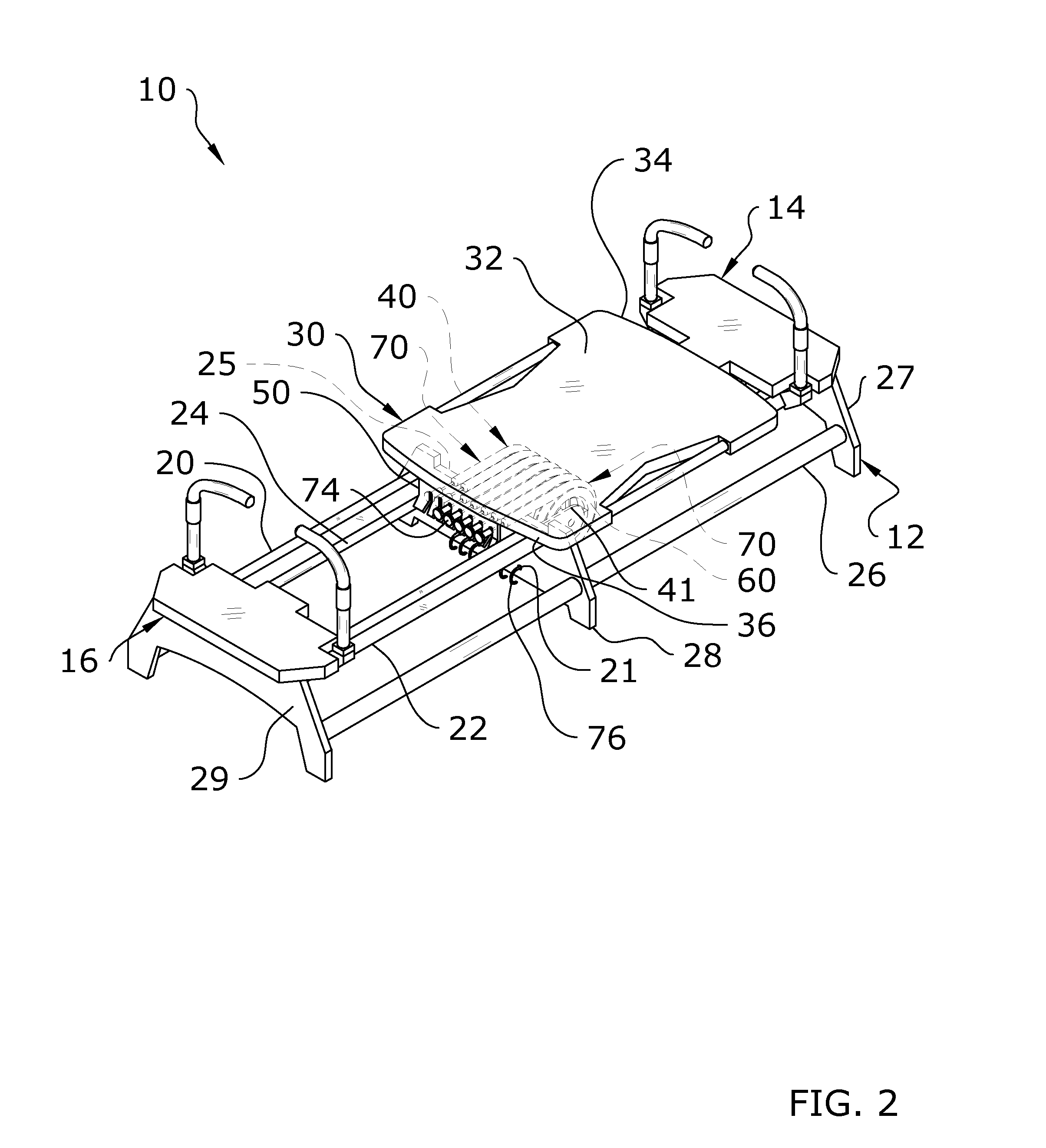
[0035]Turning now descriptively to the drawings, in which similar reference characters denote similar elements throughout the several views, FIGS. 1 through 20 illustrate a frame 12, a platform 32 movably positioned upon the frame 12 and a tension assembly 40 connected between the frame 12 and the platform 32 to provide selective tension upon the platform 32 in a first direction. The tension assembly 40 is comprised of a plurality of pulleys 60 and a plurality of tension devices 70 positioned upon the pulleys 60, wherein the tension devices 70 are attached between a frame 12 and the platform 32. The tension members are selectively engaged to the platform 32 to increase or decrease the tension applied to the platform 32 for varying levels of workouts. The combination of the frame 12 and the platform 32 of the present invention preferably form a Pilates exercise machine.

B. Exercise Machine

[0036]FIGS. 1 through 3b illustrate an exercise machine 10. The exercise machine 10 is...


PUM


Abstract

A Pilates machine tension device support system for efficiently providing a tension force to a movable platform of an exercise machine. The Pilates machine tension device support system generally includes a frame, a platform movably positioned upon the frame and a tension assembly connected between the frame and the platform to provide selective tension upon the platform in a first direction. The tension assembly is comprised of a plurality of pulleys and a plurality of tension devices positioned upon the pulleys, wherein the tension devices are attached between a frame and the platform. The tension members are selectively engaged to the platform to increase or decrease the tension applied to the platform for varying levels of workouts.

Description

CROSS REFERENCE TO RELATED APPLICATIONS[0001]I hereby claim benefit under Title 35, United States Code, Section 119(e) of U.S. provisional patent application Ser. No. 61 / 719,757 filed Oct. 29, 2012. The 61 / 719,757 application is currently pending. The 61 / 719,757 application is hereby incorporated by reference into this application.[0002]I hereby claim benefit under Title 35, United States Code, Section 119(e) of U.S. provisional patent application Ser. No. 61 / 719,763 filed Oct. 29, 2012. The 61 / 719,763 application is currently pending. The 61 / 719,763 application is hereby incorporated by reference into this application.STATEMENT REGARDING FEDERALLY SPONSORED RESEARCH OR DEVELOPMENT[0003]Not applicable to this application.BACKGROUND OF THE INVENTION[0004]1. Field of the Invention[0005]The present invention relates generally to a Pilates exercise machine and more specifically it relates to a Pilates machine tension device support system for efficiently providing a tension force to a m...

Claims


Application Information

Patent Timeline
IPC IPC(8): A63B21/02
CPCA63B21/02A63B21/0557A63B21/154A63B21/0428A63B21/0552A63B22/0089A63B21/00065A63B23/02A63B21/4033A63B21/4045A63B21/0442A63B21/4035A63B21/023
Inventor LAGREE, SEBASTIEN ANTHONY LOUIS
Owner LAGREE TECH INC
Learn More