Unwind and feed system for elastomeric thread

a technology of elastomeric thread and feed system, which is applied in the direction of shuttles, instruments, printers, etc., can solve the problems of substantial scrap production during shut-down and start-up, substantial down-time losses, and the manufacturing process must be shut down every time, so as to eliminate the remaining tension variation, reduce the effect of tension variation and smoothing out tension variation

Active Publication Date: 2010-03-25
HARTZHEIM ENG
View PDF32 Cites 5 Cited by
  • Summary
  • Abstract
  • Description
  • Claims
  • Application Information

AI Technical Summary

Benefits of technology

[0030]In general, this invention provides an overend unwind system which is especially adapted for unwinding tacky elastomeric fiber threads such as uncoated spandex thread, damping out the ballooning affect and major tension spikes of the thread shortly after the thread leaves the spool, applying a first coarse tension control on the thread in the vicinity of where the thread leaves the spool, feeding the unwound thread to a nip in a manufacturing operation, and applying a second refining tension control to the thread adjacent where the thread enters the manufacturing nip. The unwind system thus smoothes out tension variations in the unwound thread using a such two-stage tension-control system, wherein the first-stage coarse-tension control reduces tension variations along the length of the thread and the second-stage fine-tension control further reduces and / or eliminates the remaining tension variations and sets the thread tension to the desired value proximate the location where the thread enters the product assembly operation. Thus, the 2-stage tension control system of the invention acts like an extended-length 2-stage shock absorber, effective to substantially dampen the tension variations which exist in the thread as the thread leaves the spool. With the exception of a tension sensor, all thread guide surfaces encountered by the thread after leaving the spool, and while the thread is under tension, are moving surfaces, such that the tensioned thread, using apparatus and processes of the invention, never passes over a static guide surface other than the tension sensor, and thereby experiences a reduced level of drag as the thread traverses its thread path from the spool to the manufacturing nip.
[0036]In some embodiments, the terminal tensioning device has a target setpoint, and wherein the setpoint is adjustable thereby to increase or decrease a setpoint tension at which such thread leaves the terminal tensioning device.
[0076]In a fifth family of embodiments, the invention comprehends an unwind and feed system adapted for overend unwinding of an elastic thread from a package of such thread, and feeding such unwound thread in a downstream direction, along a thread feed path, to a downstream operation, the unwind and feed system comprising a frame, including a thread holder adapted to hold a package of thread; a thread capture assembly located proximate such thread holder, and spaced from the thread holder a distance which facilitates the thread capture assembly capturing a loping thread which is being drawn overend off such package of thread, the thread capture assembly being effective to receive a loping thread from such package of thread and to substantially attenuate transverse movements of such loping thread, the capture assembly comprising a plurality of capture devices, all interaction of such thread with the capture devices comprising such thread contacting only moving surfaces of the capture devices; and a thread tension control system comprising (i) first-stage thread tensioning device proximate and downstream from the thread capture assembly, and (ii) second-stage thread tensioning device spaced at least 3 meters, along the thread feed path, downstream from the first-stage tensioning device and located within 3 meters of a locus where thread traversing the unwind and feed system enters such downstream operation.

Problems solved by technology

A major disadvantage of a rolling such unwind operation is that the manufacturing process must be shut down every time a spool of thread is exhausted.
Since the manufacturing process typically draws a plurality of material feeds from a plurality of source packages of thread, shutting down the entire manufacturing process when a single source is exhausted typically results in substantial down-time losses and substantial production of scrap during shut-down and start-up.
The result is the wasting of the thread which remains on those spools which are not exhausted.
However, overend unwinding and feeding technology has its own challenges to successful operation.
But there is no sensing, no direct control, of the tension in individual ones of the threads leaving the driven roll.
And there is no control of tension in the threads between the driven roll and the manufacturing nip where the threads enter the product assembly operation.
Overall, in conventional overend technology, the tension entering the manufacturing nip is not well controlled by controlling the speed or tension at a driven roll which is close to the elastic fiber spool and relatively farther from the manufacturing nip.
A further problem with conventional unwind systems is that the ceramic eye, which is first encountered by the thread as the thread leaves the spool, is motionless, and thus exerts a static friction drag on the loping, jump-rope, thread which is passing through the eye.
Thus, a significant drag results when this very tacky thread is pulled across the static ceramic surface of the eye guide.
Therefore, the amount of friction at the static eye is constantly changing, resulting in alternating large and sudden increases and decreases in tension, and accompanying sticking and slipping of the thread at the ceramic eye.
The resulting friction is neither constant nor predictable, whereby the thread is also experiencing ongoing and constant substantial changes in speed of advance of the thread along the thread path.
However none of such devices provide for integration of the tensioning devices with the industrial programmable logic controllers (PLC's) which are standard in automated manufacturing processes.
Conventional, off-the-shelf tensioning devices require direct or local input of control parameters into the individual devices, and thus do not conform to such centralized control scheme, and are therefore prohibited from use in many manufacturing environments.
Production lines used in the manufacture of hygiene, baby diaper, adult incontinent, and related products are complex, with highly sophisticated control systems.
Due to the complexity of the programming in the main system PLC, it is a difficult, time-consuming, and expensive process to make significant program changes to a functioning production line.

Method used


Image

  • Unwind and feed system for elastomeric thread
  • Unwind and feed system for elastomeric thread
  • Unwind and feed system for elastomeric thread

Examples


Embodiment Construction

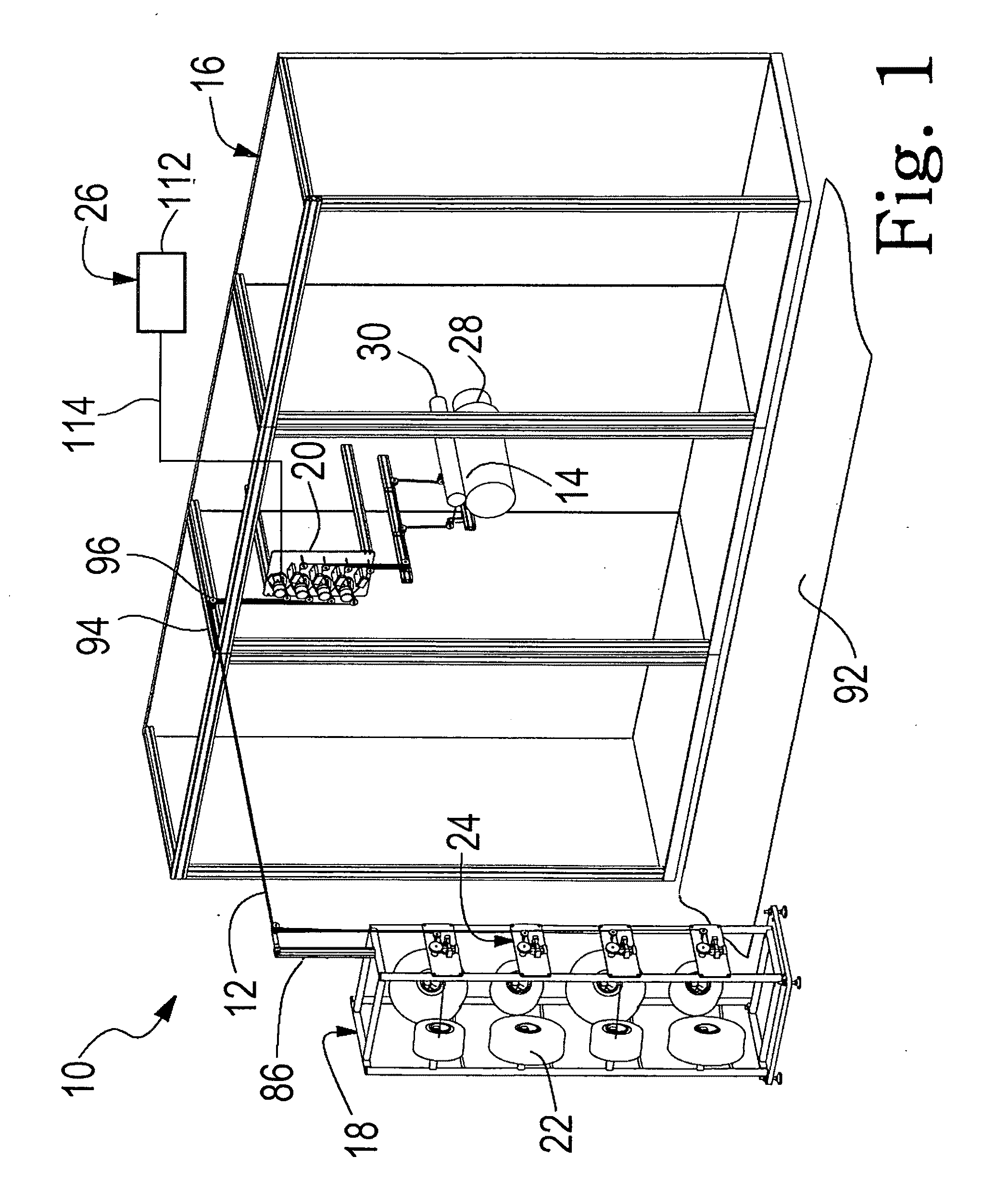
[0108]FIG. 1 illustrates a typical layout of an unwind system 10 of the invention, feeding thread 12 into a nip 14, where the nip represents the location where the thread joins a product assembly operation 16. Unwind system 10 includes a creel 18 and a final tension control system 26. Creel 18 holds a plurality of spools 22 of thread to be unwound and fed into the product assembly operation. Creel 18 has a first-stage control system 24. The primary controlling elements of final tension control system 26 are mounted on a delivery platform 20. The product assembly operation 16 is generally represented by a first manufacturing process roll 28 and a second manufacturing process roll 30 which collectively define manufacturing nip 14 where threads treated according to the unwind system of the invention enter the product assembly operation.

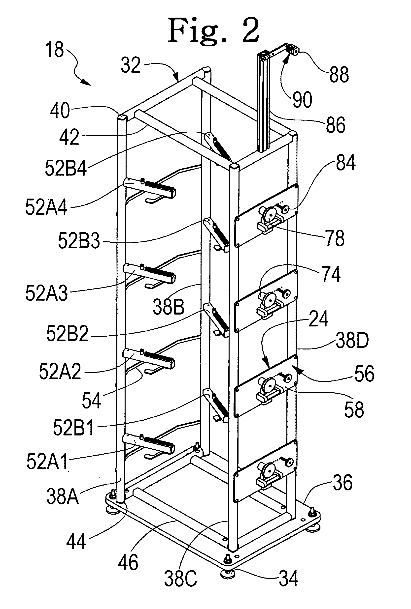
[0109]Turning now to FIGS. 2 and 3, creel 18 has a metal e.g. steel frame 32 which is supported from the floor or other underlying surface by a pluralit...


PUM


Abstract

An overend unwind system for unwinding tacky elastomeric fiber threads such as uncoated spandex thread, capturing the ballooning affect of the thread as the thread leaves the spool, applying a first-stage tension control on the thread adjacent where the thread leaves the spool, feeding the unwound thread to a nip in a downstream process, and applying a final tension increment to the thread adjacent where the thread enters the downstream process. All thread guide surfaces encountered by the thread after leaving the spool, and while the thread is under designed operating tension, are moving surfaces, such that the tensioned thread thereby experiences a reduced level of drag as the thread traverses its path of travel from the spool to the downstream process.

Description

BACKGROUND[0001]This invention relates generally to unwind devices and feed controls which are used for unwinding highly elastic and tacky threads from a spool / package of such thread, and feeding such threads into a manufacturing process which uses and / or further processes such threads.[0002]In general, a spool / package of the desired thread is mounted on an unwind stand. Thread from the spool / package is threaded by hand into the manufacturing process at process start-up. As the manufacturing process which uses the thread proceeds, thread is pulled from the package and guided to the manufacturing process.[0003]One method of unwinding and feeding thread from a spool of such thread in manufacturing processes is referred to as a “rolling unwind”. In the rolling unwind method, the package / spool is mounted in an unwind stand with the axis of rotation of the package / spool oriented generally perpendicular to the direction in which the thread is to be drawn from the package. The spool / packag...

Claims


Application Information

Patent Timeline
Patent Type & Authority Applications(United States)
IPC IPC(8): B65H57/18B65H59/10B65H59/16B65H49/02
CPCB65H49/06B65H49/16B65H51/04B65H57/14B65H57/16D02H13/24B65H59/388B65H2555/23B65H2701/31B65H2701/319D02H1/00B65H59/16
Inventor HARTZHEIM, RICHARD J.
Owner HARTZHEIM ENG
Why Eureka
Try Eureka