Cable connector for use in a brake actuating system

a technology of cable connector and brake actuating system, which is applied in the direction of shaft, coupling, rod connection, etc., can solve the problems of dislodging of the enlarged head, increasing the cost of providing the clevis and attaching it to the output member, etc., and achieves the effect of increasing and reducing the tension in the cable system, increasing and reducing the tension

Active Publication Date: 2012-01-17
VENTRA GRP
View PDF35 Cites 4 Cited by
  • Summary
  • Abstract
  • Description
  • Claims
  • Application Information

AI Technical Summary

Benefits of technology

[0006]The output side cable connector is connected to the distal end of the input cable and is constructed to operatively connect the input cable to the cable system of the vehicle. The input side cable connector includes a cable connector portion connected to the proximal end of the input cable, and an actuator connector portion extending generally transversely to a longitudinal extent of the input cable. The input side cable connector also includes a wear protector attached to one of the actuator connector portion and the surface defining the receiving space on the output member. The wear protector is formed of a wear resistant material. The input side cable connector is constructed to operatively connect the input cable to the actuator to enable movement of the output member in the brake applying and releasing directions thereof to increase and decrease the tension in the cable system via the input cable and the output side cable connector when the output side cable connector operatively connects the input cable to the cable system as aforesaid. This is done by the actuator connector portion being received in the receiving space of the output member with the wear protector in engagement with the other of the actuator connector portion and the surface defining the receiving space on the output member. This enables relative movement between the actuator connector portion and the output member as the output member is moved in the brake applying and releasing directions thereof.
[0007]Yet another aspect of the invention provides a brake actuating system with a wear protector in combination with a motor vehicle having brakes that are actuated to prevent vehicle wheel rotation and hence rolling movement of the vehicle. The brake actuating system in this combination comprises an actuator including a metal output member movable in a brake applying direction and a brake releasing direction. The metal output member includes a surface defining a receiving space. The brake actuating system also comprises a cable system operatively connected to the brakes such that increasing tension in the cable system actuates the brakes, and then decreasing tension in the cable system de-actuates the brakes. The cable system includes an input cable. A cable connector includes a cable connector portion connected to a proximal end of the input cable, and an actuator connector portion extending generally transversely to a longitudinal extent of the input cable. The cable connector also includes a wear protector attached to one of the actuator connector portion and the surface defining the receiving space. The wear protector is formed of a wear resistant material. The cable connector operatively connects the input cable to output member of the actuator to enable movement of the output member in the brake applying and releasing directions thereof to increase and decrease the tension in the cable system via the input cable. This is done by the actuator connector portion being received in the receiving space of the output member with the wear protector in engagement with the other of the actuator connector portion and the surface defining the receiving space. This enables relative movement between the actuator connector portion and the output member as the output member is moved in the brake applying and releasing directions thereof.

Problems solved by technology

One particular shortcoming of this approach is the expense of providing the clevis and attaching it to the output member.
Also, the clevis presents a situation where the enlarged head may become dislodged.

Method used


Image

  • Cable connector for use in a brake actuating system
  • Cable connector for use in a brake actuating system
  • Cable connector for use in a brake actuating system

Examples


Embodiment Construction

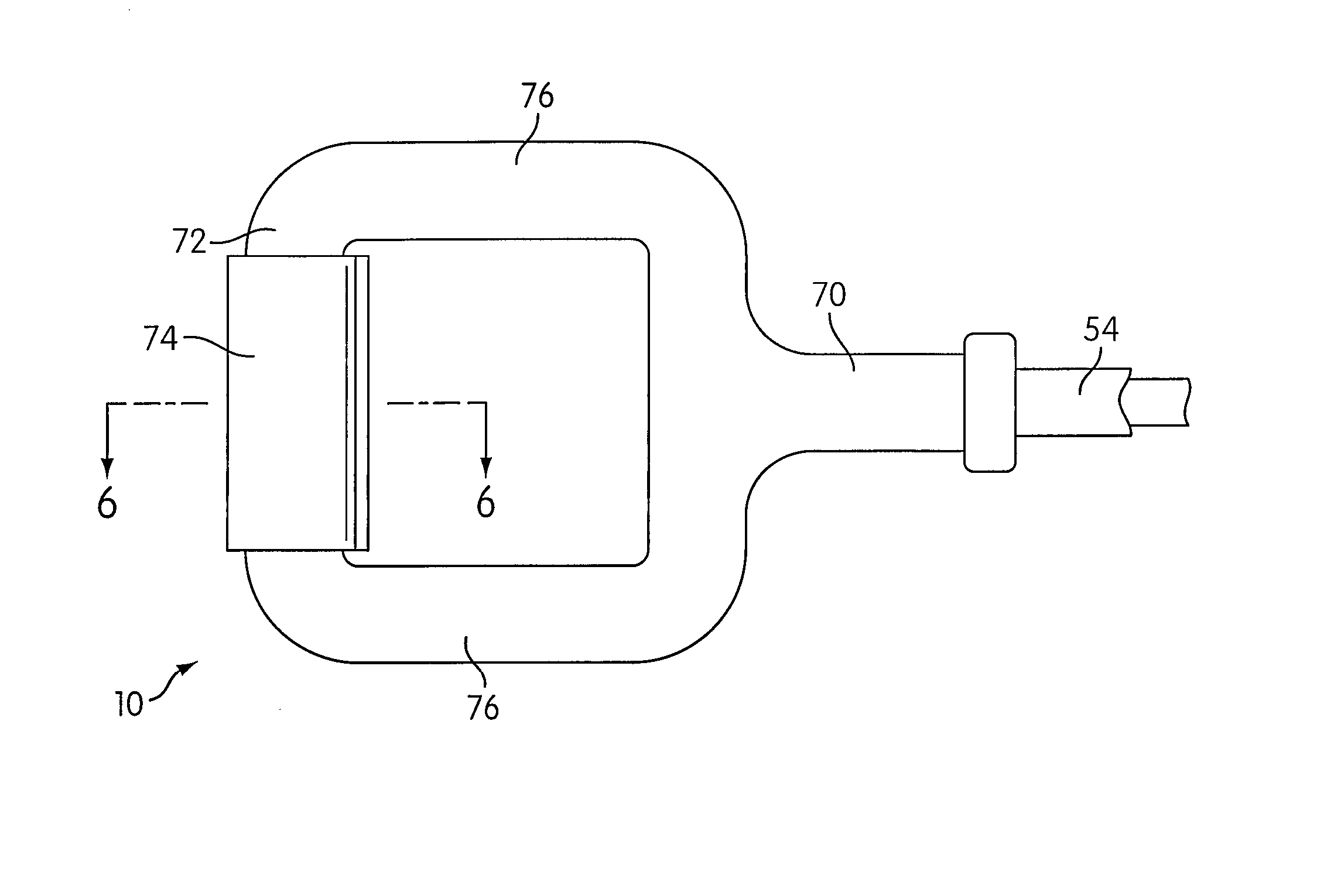
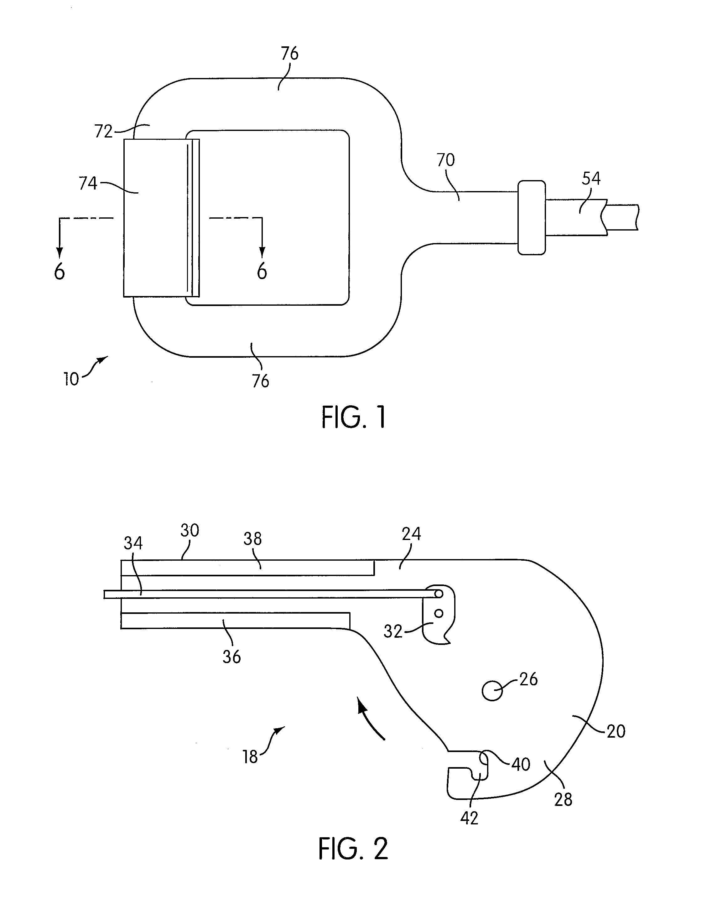
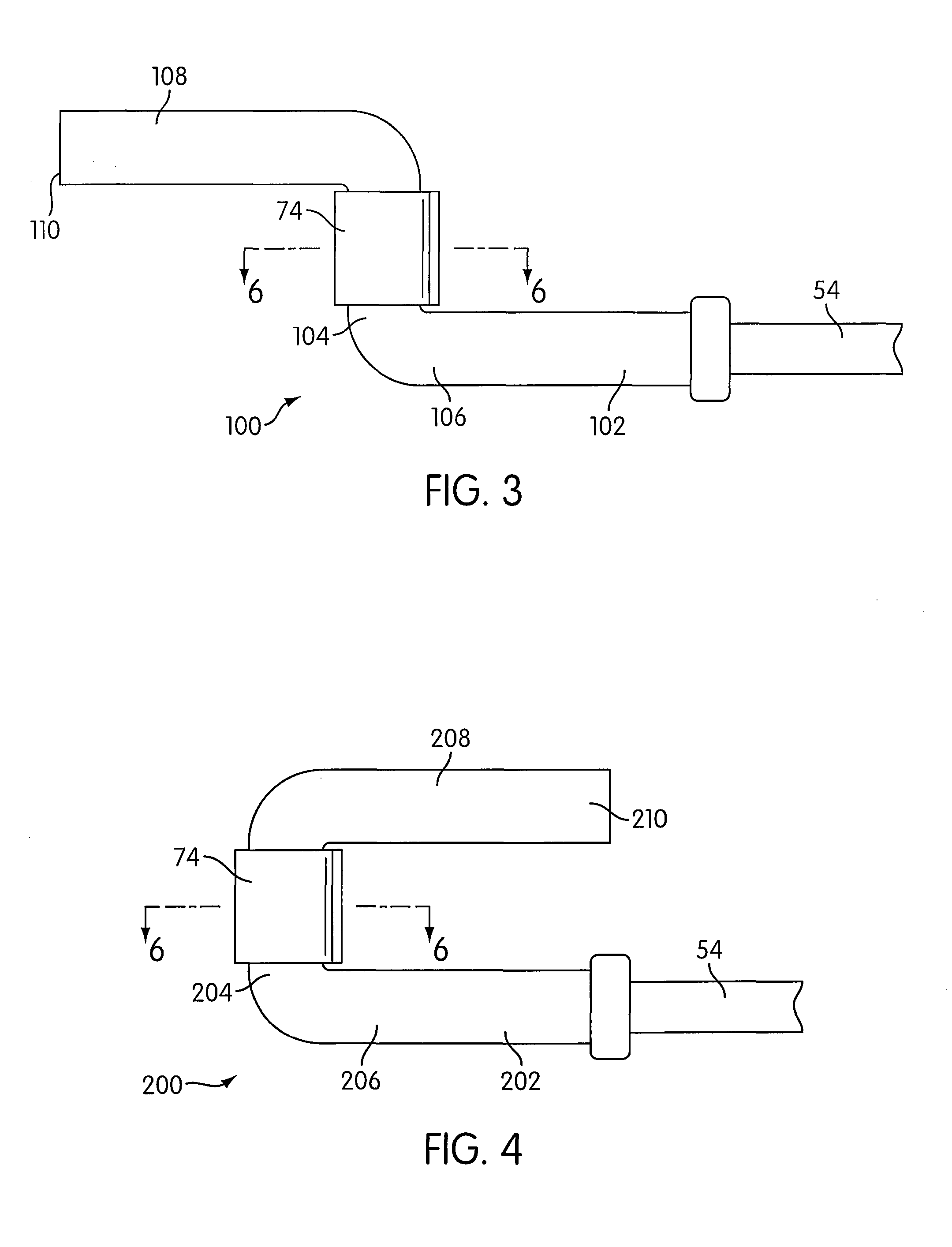
[0022]FIG. 1 illustrates a cable connector 10 that is designed to be used in a brake actuating system 12, and FIGS. 3 and 4 illustrate alternative connectors 100, 200. The brake actuating system 12 is illustrated schematically in FIG. 8 in a motor vehicle 14 that has brakes 16 that are actuated to prevent rotation of vehicle wheels 17 and hence rolling movement of the vehicle 14.

[0023]The brake actuating system 12 comprises an actuator 18 that may be of any type, and may be either power-operated, hand-operated (i.e., by a hand lever mounted adjacent the driver's seat in the passenger compartment), or foot-operated (i.e., by a pedal assembly mounted beneath the dashboard in front of the driver's seat). Such an actuator 18 includes a metal output member 20 movable in a brake applying direction and a brake releasing direction. In the figures, and particularly FIGS. 2 and 5, the actuator 18 is of the hand-operated type including a lever 24 that pivotally mounts to a fixed mounting brack...


PUM


Abstract

The present application discloses a cable connector for use in attaching an input cable to an actuator in a vehicle braking system.

Description

FIELD OF THE INVENTION[0001]The present invention relates to a cable connector for use in attaching an input cable to an actuator in a vehicle brake actuating system.BACKGROUND OF THE INVENTION[0002]In many brake actuators, the input cable for the cable system is attached to an output member of the actuator by using a pivoted clevis that receives an enlarged head on the proximal end of the input cable. One particular shortcoming of this approach is the expense of providing the clevis and attaching it to the output member. Also, the clevis presents a situation where the enlarged head may become dislodged. However, the use of this approach does have some advantages. Specifically, the pivotal mounting of the clevis enables it to adjust itself as the output member rotates so that it is in line with the input cable.[0003]The invention of the present application endeavors to provide an improved and / or more cost-effective construction for connecting an input cable to the output member of a...

Claims


Application Information

Patent Timeline
Patent Type & Authority Patents(United States)
IPC IPC(8): F16D65/14
CPCF16D65/14F16D2121/14Y10T74/20462Y10T403/57F16D2125/62
Inventor HERMAN, RYANSYKES, MICHAELREVELIS, PETER
Owner VENTRA GRP
Why Eureka
Try Eureka