Low-cost destruct type non-contact antitank unmanned aerial vehicle

An unmanned aerial vehicle and anti-tank technology, applied in unmanned aerial vehicles, motor vehicles, aircraft parts, etc., can solve the problems of easy exposure of the launcher's position, exposure of the launch position, and high cost. It is not complicated and difficult to achieve. Expose operator's position, low cost effect

Pending Publication Date: 2018-05-29
长沙深蓝未来智能技术有限公司
View PDF0 Cites 1 Cited by
  • Summary
  • Abstract
  • Description
  • Claims
  • Application Information

AI Technical Summary

Benefits of technology

This invention relates to an aircraft that has its own ability to fight deterring attacks on other objects like cars, boats, military equipment, etc., without requiring expensive bullets for defense purposes.

Problems solved by technology

The technical problem addressed in this patented text relates to finding ways to protect rockets during direct fire attacks on military bases without adding extra weight that could affect their performance.

Method used


Image

  • Low-cost destruct type non-contact antitank unmanned aerial vehicle

Examples


Embodiment Construction

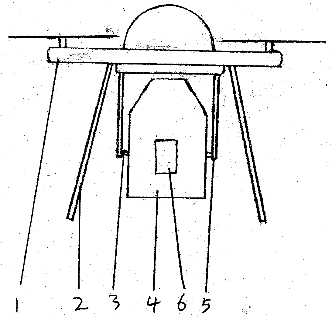
[0014] 1. Two on the bottom of the drone 2. Two 5. brackets are installed between the landing gear, 5. The top of the bracket is connected by 3. the rotating shaft 4. The side of the explosive forming bomb, 4. The side of the explosive forming bomb is connected with 6. Aiming 4. Explosive shaped bombs cannot exceed 2. Landing gear.

[0015] When in use, make 1. the UAV fly to the sky above or near the target and face the target. The target distance is within the effective damage range of 4. the explosively formed projectile. Control the rotation of the 3. rotating shaft so that the trajectory of the 4. explosively formed projectile is aligned. After the target, control 4. Explosive shaped projectile detonates, damages the target, and at the same time 1. The drone self-destructs.


PUM


Abstract

The invention provides a low-cost destruct type non-contact antitank unmanned aerial vehicle. A support is mounted at the bottom of an unmanned helicopter, and a rotary shaft on the support is connected to the two sides of an explosive forming bomb, wherein a video gunsight is mounted on the side face of the explosive forming bomb. In the using process, the unmanned aerial vehicle is controlled tofly to the position above a target or the side face of the target, the explosive forming bomb is exploded after the target is aimed, the formed forming pill damages the target, and the unmanned aerial vehicle is destructed. Ground or water surface targets such as a vehicle, a tank armored car, a warship and a fortification can be attacked from above or the side face, an aerial target can be attacked as well, the technology is not complex, the cost is low, and the position of an operator is not exposed.

Description


Claims


Application Information

Patent Timeline
Owner 长沙深蓝未来智能技术有限公司
Why Eureka
Try Eureka