A crankcase ventilation pipe detection device and method

A technology for crankcase ventilation and pipe detection, which is applied in the direction of crankcase ventilation, engine measuring devices, machines/engines, etc., and can solve problems such as polluting the environment and disconnecting joints

Active Publication Date: 2019-10-29
NINGBO GEELY ROYAL ENGINE COMPONENTS
View PDF1 Cites 0 Cited by
  • Summary
  • Abstract
  • Description
  • Claims
  • Application Information

AI Technical Summary

Problems solved by technology

[0008] The existing ventilation pipe is directly connected to the crankcase and the outlet pipe of the air filter, wherein the ventilation pipe and the outlet pipe of the crankcase and the air filter are mainly connected by a quick-plug joint, fixed by a hoop or assembled by an interference fit. Due to the aging of joint parts, impact by external force, etc., the joints are easy to fall off, which will cause oil vapor and gasoline vapor to directly enter the air and pollute the environment, and unfiltered air will enter the engine and cause cylinder explosion.

Method used


Image

  • A crankcase ventilation pipe detection device and method
  • A crankcase ventilation pipe detection device and method

Examples


Embodiment 1

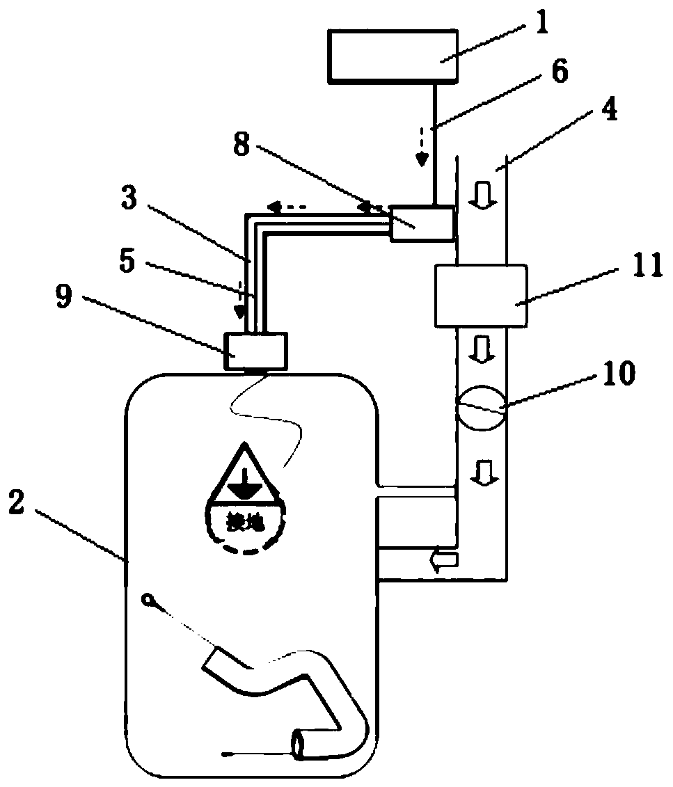
[0031] This embodiment discloses a crankcase ventilation pipe detection device, which includes a vehicle-mounted computer 1, a crankcase 2, a crankcase ventilation pipe 3, a detection conductor 5 and a connecting wire 6, and the crankcase ventilation pipe 3 has a first connection end and the second connection end, the first connection end of the crankcase ventilation pipe 3 is connected with the intake device 4, and its second connection end is connected with the crankcase 2, and the crankcase 2 is connected with the on-board computer 1 The detection conductor 5 is arranged on the crankcase ventilation pipe 3 and extends from the first connection end of the crankcase ventilation pipe 3 to the second connection end. One end of the detection conductor 5 is connected to the crankcase ventilation pipe 3. 2, the other end is connected to one end of the connecting wire 6, and the other end of the connecting wire 6 is connected to the on-board computer 1.

[0032] The detection condu...

Embodiment 2

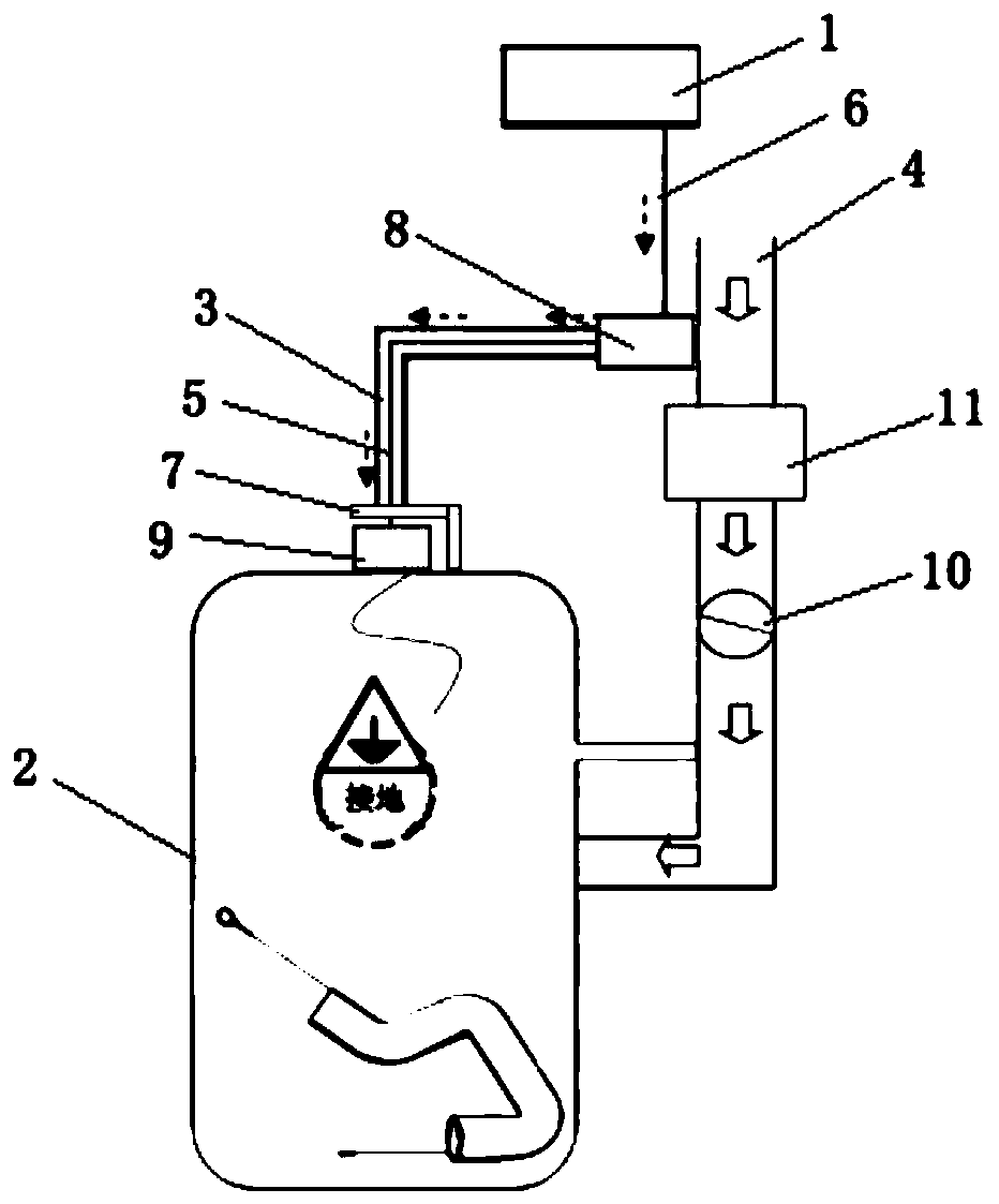
[0040] The crankcase ventilation pipe detection device provided in this embodiment includes an on-board computer 1, a crankcase 2, a crankcase ventilation pipe 3, a detection conductor 5, a conduction bracket 7 and a connecting wire 6, and the crankcase ventilation pipe 3 has a first connection end and the second connection end, the first connection end of the crankcase ventilation pipe 3 is connected with the intake device 4, and its second connection end is connected with the crankcase 2, and the crankcase 2 is connected with the on-board computer 1 Connected, the conduction bracket 7 is connected with the crankcase 2, and is close to the second connection end of the crankcase ventilation pipe 3; the detection conductor 5 is arranged on the crankcase ventilation pipe 3, and from the crankcase ventilation pipe 3 The first connecting end of the crankcase ventilation pipe 3 extends to the second connecting end, one end of the detection conductor 5 is connected to the conducting ...

Embodiment 3

[0046] The crankcase ventilation pipe detection device provided in this embodiment includes an on-board computer 1, a crankcase 2, a crankcase ventilation pipe 3, a detection conductor 5, a conduction bracket 7 and a connecting wire 6, and the crankcase ventilation pipe 3 has a first connection end and the second connection end, the first connection end of the crankcase ventilation pipe 3 is connected with the intake device 4, and its second connection end is connected with the crankcase 2, and the crankcase 2 is connected with the on-board computer 1 Connected, the conduction bracket 7 is connected with the crankcase 2, and is close to the second connection end of the crankcase ventilation pipe 3; the detection conductor 5 is arranged on the crankcase ventilation pipe 3, and from the crankcase ventilation pipe 3 The first connecting end of the crankcase ventilation pipe 3 extends to the second connecting end, one end of the detection conductor 5 is connected to the conducting ...


PUM


Abstract

The invention relates to the technical field of internal combustion engines, and particularly discloses a detection device and method of a ventilation pipe of a crankcase. A detection conductor is additionally arranged on the ventilation pipe of the crankcase and is connected into a vehicle-mounted computer of a vehicle to form a detection circuit. On-off of connection between the detection conductor and a communicating wire and / or a breakover support is utilized for indicating the connecting state of the ventilation pipe of the crankcase. Under the condition of normal connection of the ventilation pipe of the crankcase, the detection circuit is an access. Under the condition that any end of the ventilation pipe of the crankcase falls off, the detection circuit is switched off, and the detection circuit can be displayed through the vehicle-mounted computer so as to remind a user in time. By means of the detection device and method, the connecting state of joints of the ventilation pipeof the crankcase can be effectively detected, the advantages of low cost and convenient implementation are achieved, and the detection device and method are suitable for the improvement of an existing ventilation pipe of a crankcase.

Description

technical field [0001] The invention relates to the technical field of internal combustion engines, in particular to a crankcase ventilation pipe detection device and method. Background technique [0002] When the engine is working, some combustible mixed gas and exhaust gas will always escape into the crankcase through the piston ring, and the gasoline vapor condensed into the crankcase will make the engine oil thinner and the performance will deteriorate. The exhaust gas contains water vapor and sulfur dioxide. The water vapor condenses in the engine oil to form foam, which destroys the oil supply. This phenomenon is especially serious in winter; sulfur dioxide meets water to form sulfurous acid, and sulfurous acid meets oxygen in the air to form sulfuric acid. These acidic substances The appearance of oil not only deteriorates the oil, but also corrodes the parts. As the combustible mixture and exhaust gas escape into the crankcase, the pressure in the crankcase will inc...

Claims


Application Information

Patent Timeline
Patent Type & Authority Patents(China)
IPC IPC(8): F01M13/00F02B77/08
CPCF01M13/00F01M2250/00F02B77/08
Inventor 王丰王超魏庆山肖翔刘东赵福成王瑞平
Owner NINGBO GEELY ROYAL ENGINE COMPONENTS
Why Eureka
Try Eureka