High-safety electrical appliance electrifying assembly

A technology of safety and electrical appliances, applied in the field of electrical energization components, can solve the problems of electrical power failure, hidden dangers, electrical damage, etc., and achieve the effects of high electrical safety, convenient use and simple structure

Inactive Publication Date: 2018-06-01
泉州市鸿远电子科技有限公司
View PDF0 Cites 15 Cited by
  • Summary
  • Abstract
  • Description
  • Claims
  • Application Information

AI Technical Summary

Problems solved by technology

[0002] Electrical appliances need to be connected to electricity when they are in use. Electrical appliances are generally connected to plug connectors. When power is needed, the plug connectors are inserted into socket sockets to achieve power. , the power supply piece is exposed in the socket slot, the plug piece of the plug connector inserted into the socket slot will contact the power supply piece, and the power supply piece is directly connected to the mains, so the power supply piece can be said to be directly exposed On the outside, there is a great potential safety hazard. Moreover, when the traditional plug connector is inserted into the socket slot, it only relies on friction to keep it in motion. fall off from the socket, resulting in a sudden power failure of the electrical appliance, which is likely to cause damage to the electrical appliance

Method used


Image

  • High-safety electrical appliance electrifying assembly
  • High-safety electrical appliance electrifying assembly
  • High-safety electrical appliance electrifying assembly

Examples


Embodiment Construction

[0020] All features disclosed in this specification, or steps in all methods or processes disclosed, may be combined in any manner, except for mutually exclusive features and / or steps.

[0021] Any feature disclosed in this specification (including any appended claims, abstract and drawings), unless expressly stated otherwise, may be replaced by alternative features which are equivalent or serve a similar purpose. That is, unless expressly stated otherwise, each feature is one example only of a series of equivalent or similar features.

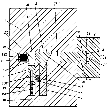
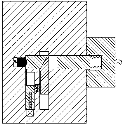
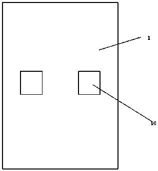
[0022] refer to Figure 1-4 , according to an embodiment of the present invention, a high-safety electrical power supply assembly includes a socket socket 1 fixedly installed in a wall and a plug connector 2 connected to an electrical appliance, and the socket socket 1 is symmetrically arranged front and back There is an insertion slot 10, a telescopic slot 12 is arranged in the left end wall of the insertion base 10, and a power supply colum...


PUM


Abstract

The invention discloses a high-safety electrical appliance electrifying assembly. The electrical appliance electrifying assembly comprises an inserting-connecting socket fixedly mounted in a wall body, and an inserting-connecting plug connected with an electrical appliance, wherein inserting-connecting grooves are formed in the inserting-connecting socket in front-back symmetry; a telescopic groove is formed in the left end wall of the inserting-connecting socket; a power supply column is glidingly mounted in the telescopic groove; a first sliding groove penetrating the inserting-connecting groove is also formed in the inserting-connecting socket; a second sliding groove which extends up and down and positioned on the left side of the first sliding groove is formed in the inserting-connecting socket; a first through groove is formed between the first sliding groove and the second sliding groove; a second through groove is formed between the second sliding groove and the inserting-connecting groove; a first sliding block which can slide up and down is mounted in the first sliding groove; a second sliding block which can slide up and down is mounted in the second sliding groove; racks are arranged on the inner side end surfaces of the first sliding block and the second sliding block separately; a rotational gear is rotatably mounted in the first through groove, and the rotationalgear extends into the first sliding groove and the second sliding groove to be connected with the racks in a matching manner; and a partition plate is slidably mounted in the second through groove.

Description

technical field [0001] The invention relates to the technical field of electricity consumption and power supply of electrical appliances, in particular to a high-safety electric appliance energization component. Background technique [0002] Electrical appliances need to be connected to electricity when they are in use. Electrical appliances are generally connected to plug connectors. When power is needed, the plug connectors are inserted into socket sockets to achieve power. , the power supply piece is exposed in the socket slot, the plug piece of the plug connector inserted into the socket slot will contact the power supply piece, and the power supply piece is directly connected to the mains, so the power supply piece can be said to be directly exposed On the outside, there is a great potential safety hazard. Moreover, when the traditional plug connector is inserted into the socket slot, it only relies on friction to keep it in motion. If it falls off from the socket, it ...

Claims


Application Information

Patent Timeline
Patent Type & Authority Applications(China)
IPC IPC(8): H01R13/447H01R13/631H01R13/639H01R13/08H01R13/14
CPCH01R13/447H01R13/08H01R13/14H01R13/631H01R13/639
Inventor 陈惠金叶国年
Owner 泉州市鸿远电子科技有限公司
Why Eureka
Try Eureka