Novel LED lamp device

An LED lamp device and a new type of technology, applied in lighting devices, lighting auxiliary devices, lighting device parts and other directions, can solve the problems of reducing maintenance efficiency, complicated and complicated operations, electric shock accidents, etc., to improve maintenance efficiency and use. Electrical safety, ease of use, and the effect of increasing safety

Inactive Publication Date: 2018-06-05
永春豪田工艺品有限公司
View PDF6 Cites 0 Cited by
  • Summary
  • Abstract
  • Description
  • Claims
  • Application Information

AI Technical Summary

Problems solved by technology

LED lamps are generally fixed and connected by fastening bolts during installation. When the LED lamp is damaged and needs to be repaired, it must be disassembled with a screwdriver and other disassembly tools. The operation is cumbersome and complicated, which greatly reduces the maintenance efficiency. At the same time, The lamp holders of existing LED lamps are generally connected to the mains. During maintenance, if they accidentally come into contact with the conductive parts in the lamp holder, it is very easy to cause electric shock accidents, and there is a great potential safety hazard.

Method used


Image

  • Novel LED lamp device
  • Novel LED lamp device
  • Novel LED lamp device

Examples


Embodiment Construction

[0019] All features disclosed in this specification, or steps in all methods or processes disclosed, may be combined in any manner, except for mutually exclusive features and / or steps.

[0020] Any feature disclosed in this specification (including any appended claims, abstract and drawings), unless expressly stated otherwise, may be replaced by alternative features which are equivalent or serve a similar purpose. That is, unless expressly stated otherwise, each feature is one example only of a series of equivalent or similar features.

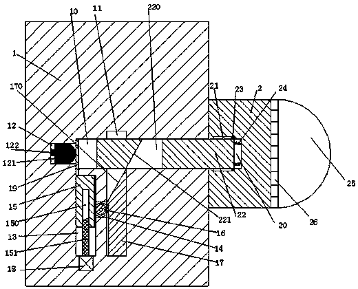
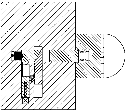
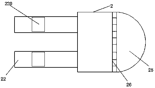
[0021] refer to Figure 1-4 , a new type of LED lamp device according to an embodiment of the present invention, including a lamp holder 1 fixedly installed in the base body and a lamp holder 2 mated with the lamp holder, and the front and rear of the lamp holder 1 are respectively provided with insertion grooves 10. The left end wall of the lamp holder 10 is provided with a push slot 12, and the power transmission contact block 121 is movabl...


PUM


Abstract

The invention discloses a novel LED lamp device. The novel LED lamp device comprises a lamp holder fixedly mounted in a base body and a lamp cap which is connected with the lamp holder in a matched mode, wherein an insertion slot is correspondingly formed in the lamp holder in the horizontal direction; a top-pushing slot is formed in the left end wall of the lamp holder; a power transmission contact piece is movably mounted in the top-pushing slot; a first slide pushing slot which passes through the insertion slot is formed in the lamp holder; a second slide pushing slot which extends up and down and is positioned in the left side of the first slide pushing slot is further formed in the lamp holder; a first opening-closing slot is formed between the first slide pushing slot and the secondslide pushing slot; a second opening-closing slot is formed between the second slide pushing slot and the insertion slot; a first slide pushing block can be mounted in the first slide pushing slot inan up-down slide pushing mode; a second slide pushing block can be mounted in the second slide pushing slot in the up-down slide pushing mode; a toothed chain is arranged on the inner side end surfaceof each of the first slide pushing block and the second slide pushing block; a toothed chain wheel can be movably mounted in the first opening-closing slot; the toothed chain wheel is put into the first slide pushing slot and the second slide pushing slot, and is connected with the toothed chain in a matched mode; and a slide pushing plate is movably mounted in the second opening-closing slot.

Description

technical field [0001] The invention relates to the technical field of LED lamps, in particular to a novel LED lamp device. Background technique [0002] As a new type of lighting source, LED lamps are gradually replacing traditional light sources and are being used more and more widely due to their long life, high luminous efficiency, multi-color and one-time light distribution and directional irradiation functions, and can work under safe voltage. . LED lamps are generally fixed and connected by fastening bolts during installation. When the LED lamp is damaged and needs to be repaired, it must be disassembled with a screwdriver and other disassembly tools. The operation is cumbersome and complicated, which greatly reduces the maintenance efficiency. At the same time, The lamp holders of existing LED lamps are generally connected to the mains. During maintenance, if they accidentally come into contact with the conductive parts in the lamp holder, it is very easy to cause a...

Claims


Application Information

Patent Timeline
Patent Type & Authority Applications(China)
IPC IPC(8): F21K9/20F21V21/02F21V19/00F21V17/12F21V17/10F21V15/02F21Y115/10
CPCF21K9/20F21V15/02F21V17/10F21V17/12F21V19/001F21V21/02F21Y2115/10
Inventor 林培双
Owner 永春豪田工艺品有限公司
Why Eureka
Try Eureka