Foldable lamp module assembly

A module and component technology, applied in the field of lighting, can solve problems such as inability to adjust, increase work intensity, fixed lighting angle of lamps, etc., and achieve the effect of flexible angle and convenient use

Inactive Publication Date: 2018-06-05
ZOPOISE TECH
View PDF8 Cites 4 Cited by
  • Summary
  • Abstract
  • Description
  • Claims
  • Application Information

AI Technical Summary

Problems solved by technology

[0002] When installing traditional lamps, the lamps are generally fixed on the fixing base, and then the fixing base is installed on the installation rod, and then fixed and installed through the installation rod. After the installation is completed, the lighting angle of the lamp is fixed and cannot be adjusted.
[0003] Therefore, after the general lamp is fixed, there is generally only one irradiation angle at the same time, which cannot meet the needs of lighting fields from different angles.
The existing conventional method is to combine multiple lamps, which solves the problem of multi-angle lighting to a certain extent, but once these lamps are fixed, it is difficult to change the angle. If you want to change the angle again, you have to disassemble and assemble again, which will greatly increase Work intensity

Method used


Image

  • Foldable lamp module assembly
  • Foldable lamp module assembly
  • Foldable lamp module assembly

Examples


Embodiment

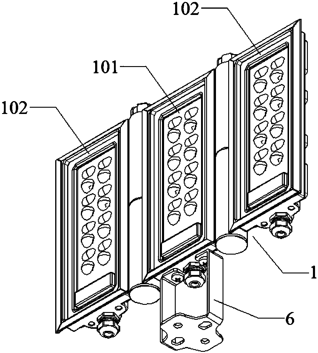
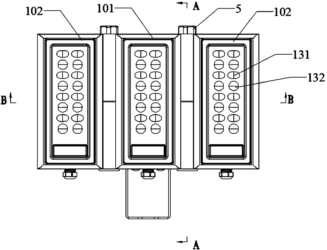
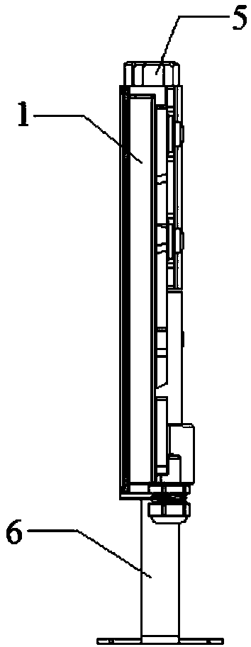
[0033] like Figure 1-5 As shown, the foldable lamp module assembly of this embodiment includes a light source module 1, and the light source module 1 includes a fixed light source module 101 and movable light source modules 102 (light source modules) located on both sides of the fixed light source module 101 The number of 1 can be changed according to actual needs, such as only 2, or 4 or 5 or more), and the fixed light source module 101 and the movable light source module 102 are connected by multiple rotating components. The rotating assembly includes a rotating shaft sleeve 2 fixed on the light source module 1 and a rotating shaft 3 inserted in the rotating shaft sleeve 2. The rotating shaft sleeve 2 includes an upper rotating shaft sleeve 201 and a lower rotating shaft sleeve 202. There is an upper rotating shaft sleeve 201 , and the movable light source module 102 is provided with a lower rotating shaft sleeve 202 matched with the upper rotating shaft sleeve 201 . Protr...


PUM


Abstract

The invention discloses a foldable lamp module assembly comprising a plurality of light source modules, wherein each light source module comprises a fixed light source module and a plurality of movable light source modules connected to the fixed light source module. The plurality of light source modules are connected through a plurality of rotating assemblies and each rotating assembly comprises arotating shaft sleeve fixedly disposed on the light source module and a rotating shaft inserted in the rotating shaft sleeve. The rotating shaft sleeve comprises an upper rotating shaft sleeve and alower rotating shaft sleeve, the upper rotating shaft sleeve and the lower rotating shaft sleeve are respectively fixedly disposed between the adjacent light source modules, the rotating shaft is provided with protruding strips, and a plurality of grooves matched with the protruding strips and used for determining the rotating angle of the light source modules. The light source modules of the foldable lamp module assembly can rotate to achieve multi-angle illumination. In addition, the angle between the light source modules is adjusted by the rotating assemblies more flexibly, more conveniently and more reliably, and the use is more convenient.

Description

technical field [0001] The invention belongs to the field of lighting, in particular to a lamp. Background technique [0002] When installing traditional lamps, the lamps are generally fixed on the fixing base, and then the fixing base is installed on the installation rod, and then fixed and installed through the installation rod. After the installation is completed, the lighting angle of the lamp is fixed and cannot be adjusted. . [0003] Therefore, after the general lamp is fixed, there is generally only one illumination angle at the same time, which cannot meet the fields that require illumination from different angles. The existing conventional method is to combine multiple lamps, which solves the problem of multi-angle lighting to a certain extent, but once these lamps are fixed, it is difficult to change the angle. If you want to change the angle again, you have to disassemble and assemble again, which will greatly increase Work intensity. Contents of the inventio...

Claims


Application Information

Patent Timeline
Patent Type & Authority Applications(China)
IPC IPC(8): F21S8/00F21V19/02F21V21/30F21V5/04F21V31/00
CPCF21S8/00F21V5/04F21V19/02F21V21/30F21V31/005
Inventor 皮远军徐连城张勇
Owner ZOPOISE TECH
Why Eureka
Try Eureka