An anti-rotation screw that can match the depth of the hole
What is Al technical title?
Al technical title is built by PatSnap Al team. It summarizes the technical point description of the patent document.
A technology of matching holes and screws, applied in the directions of screws, bolts, nuts, etc., can solve the problems that the screws cannot be freely matched with the depth, the screws cannot be placed in reverse rotation, and the connected structure collapses, so as to achieve the effect of solving the structure collapse.
Active Publication Date: 2020-04-21
NINGBO QUNLI FASTENER MFG CO LTD
View PDF5 Cites 0 Cited by
Summary
Abstract
Description
Claims
Application Information
AI Technical Summary
This helps you quickly interpret patents by identifying the three key elements:
Problems solved by technology
Method used
Benefits of technology
Problems solved by technology
The general material is metal or plastic, which is cylindrical, and the surface is engraved with concave-convex grooves called threads; with the advancement of social science and technology, the mechanization and automation of industrial and agricultural production have increased rapidly, and higher requirements have been put forward for the safety of mechanical equipment. It is necessary to prevent anti-rotation of the screws, but the screws on the market cannot prevent anti-rotation, so accidents, theft, and intentional screwing out of the screws will lead to the collapse of the connected structure and cause various unpredictable consequences
[0004] Ordinary screws cannot be turned back, so accidents, theft, and intentional unscrewing of the screws will cause various unpredictable consequences, and the structure of the connection will collapse, and ordinary screws cannot freely fit holes with different depths.
Method used
Image
Click on the blue label to locate the original text in one second.
Reading with bidirectional positioning of images and text.
Examples
Embodiment Construction
[0024] The technical solutions in the embodiments of the present invention will be clearly and completely described below in conjunction with the accompanying drawings in the embodiments of the present invention. Obviously, the described embodiments are only a part of the embodiments of the present invention, rather than all the embodiments. Based on the embodiments of the present invention, all other embodiments obtained by those of ordinary skill in the art without creative work shall fall within the protection scope of the present invention.
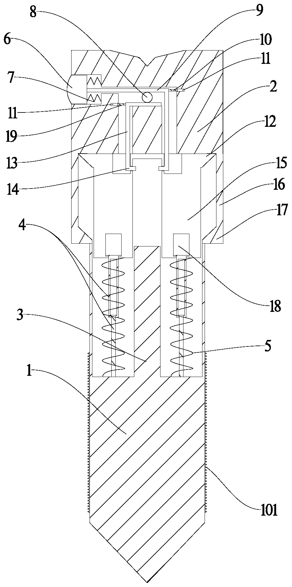
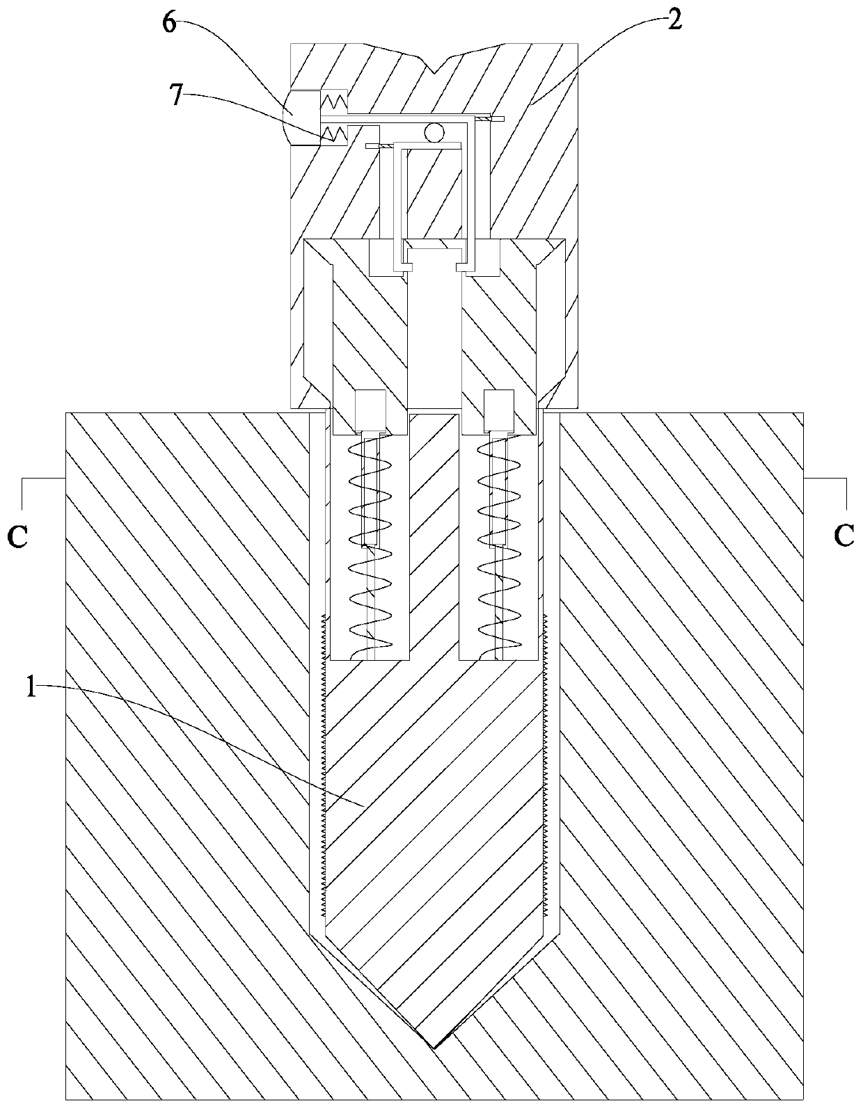
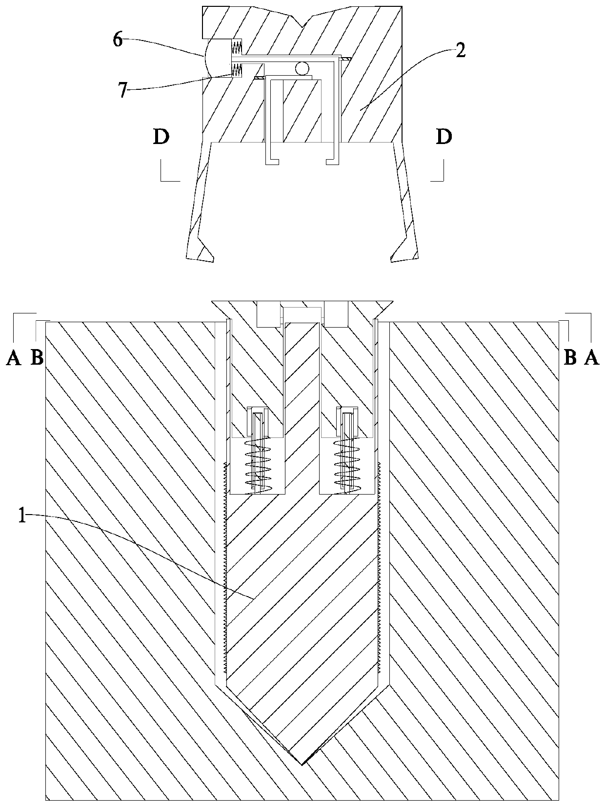
[0025] See Figure 1~7 In the embodiment of the present invention, an anti-rotation screw capable of matching the depth of the hole includes a screw 1, a screw head assembly and a return block assembly; the screw head assembly is arranged on the top of the screw 1; the screw 1 is provided with a return block Components.
[0026] The screw head assembly includes a screw head 2, a button 6, a spring A7, a gear 8, a limit rod A9, a guide col...
PUM
Abstract
The invention discloses an anti-derotation screw capable of cooperating with the hole depth. The anti-derotation screw comprises a screw body, a screw head assembly and a return stroke block assembly.The screw head assembly is arranged on the top of the screw body. The return stroke block assembly is arranged in the screw body. The screw head assembly comprises a screw head, a button, a spring A,a gear, a limiting rod A, a guide column A, an inner wall hole, a limiting rod B, a positioning protrusion, a connecting rod, a lug B and a guide column B. The return stroke block assembly comprisesa cylindrical guide rod, a telescopic rod, a spring B, an annular lug A, a return stroke block and a return stroke block bottom hole. Through the joint effect of the screw body, the screw head assembly and the return stroke block assembly, the problem of serious adverse consequences caused by structure collapse caused by screw derotation is solved; and the problem that when threads are located below a hole, the hole is deep, and a screw head is not long enough, a screw is not easily stabilized by hand when the screw is just screwed in is further solved.
Description
Technical field [0001] The invention relates to the technical field of fasteners, and in particular provides an anti-rotation screw capable of matching the depth of a hole. Background technique [0002] Fasteners are a type of mechanical parts that are used for fastening and connection and are extremely widely used. Fasteners are used in a wide range of industries, including energy, electronics, electrical appliances, machinery, chemicals, metallurgy, molds, hydraulics and other industries. All kinds of fasteners can be seen on various machinery, equipment, vehicles, ships, railways, bridges, buildings, structures, tools, instruments, chemicals, meters and supplies, etc., which are the most widely used mechanical basic parts ; It is characterized by a wide variety of specifications, different performance and uses, and a high degree of standardization, serialization, and generalization. [0003] Screws are a common fastener, widely used in machinery, electrical appliances and build...
Claims
Application Information
Patent Timeline
Application Date:The date an application was filed.
Publication Date:The date a patent or application was officially published.
First Publication Date:The earliest publication date of a patent with the same application number.
Issue Date:Publication date of the patent grant document.
PCT Entry Date:The Entry date of PCT National Phase.
Estimated Expiry Date:The statutory expiry date of a patent right according to the Patent Law, and it is the longest term of protection that the patent right can achieve without the termination of the patent right due to other reasons(Term extension factor has been taken into account ).
Invalid Date:Actual expiry date is based on effective date or publication date of legal transaction data of invalid patent.