Mounting structure of 3D printer charging tray

A technology for 3D printers and installation structures, applied to 3D object support structures, metal processing equipment, manufacturing tools, etc., can solve the problems of inconvenient operation, difficult installation and disassembly of material trays, and low efficiency, and achieve convenient disassembly and installation Effect

Inactive Publication Date: 2018-06-22
CHENGDU YUYUE TECH CO LTD
View PDF0 Cites 0 Cited by
  • Summary
  • Abstract
  • Description
  • Claims
  • Application Information

AI Technical Summary

Problems solved by technology

[0002] At present, the material tray on the 3D printer is installed on the outside, which makes it inconvenient to operate during handling and other work, and the material tray is not easy to install and disassemble, and the efficiency is low

Method used


Image

  • Mounting structure of 3D printer charging tray
  • Mounting structure of 3D printer charging tray
  • Mounting structure of 3D printer charging tray

Examples


Embodiment Construction

[0016] The specific embodiment of the present invention will be described in further detail by describing the embodiments below with reference to the accompanying drawings, the purpose is to help those skilled in the art to have a more complete, accurate and in-depth understanding of the concept and technical solutions of the present invention, and contribute to its implementation.

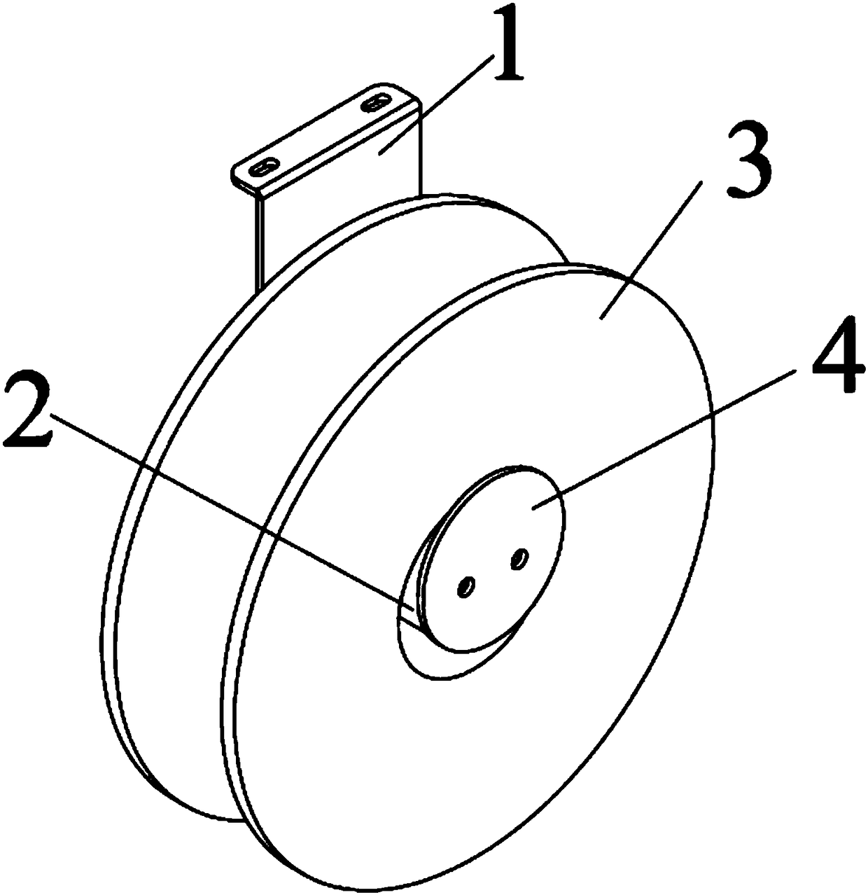
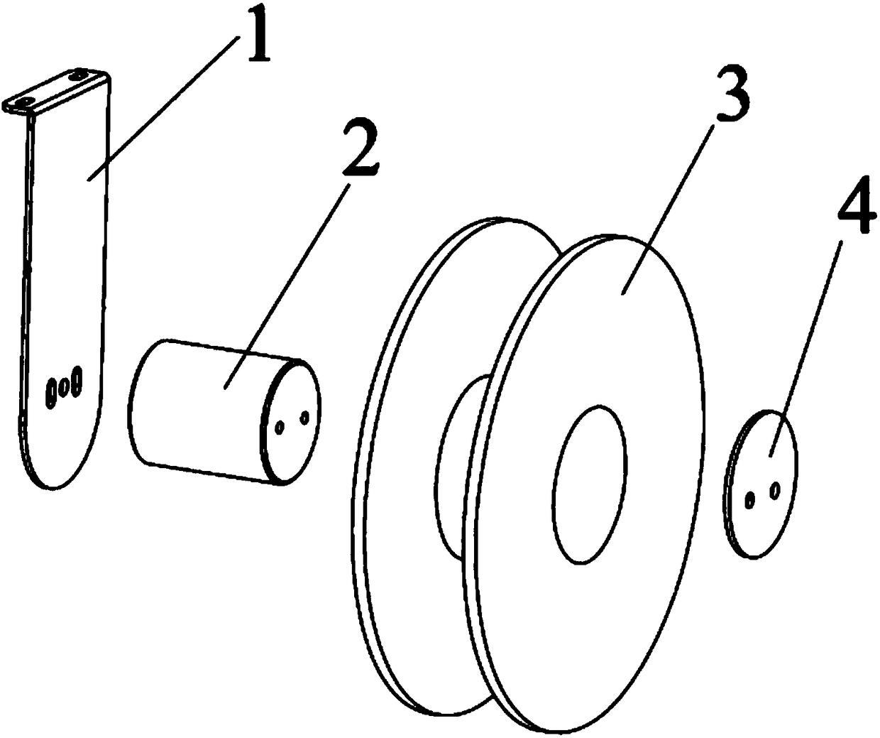
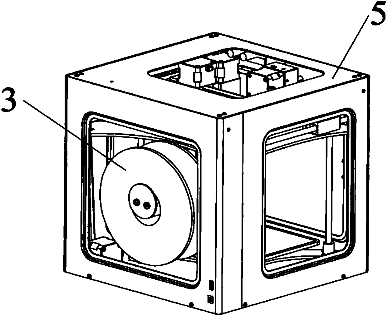
[0017] Such as Figure 1 to Figure 4 As shown, the present invention is a 3D printer tray installation structure, which is used to install the tray 3 on the printer shell 5 . The material tray 3 is used for winding printing materials. This installation structure is arranged inside the printer casing 5, so that the material tray 3 is installed inside the printer casing 5. The printer casing 5 is a rectangular shell as a whole, and the inside is hollow, so that Can accommodate tray 3.

[0018] The interior of the printer housing 5 is also provided with an inner frame, which includes a horizontal s...


PUM


Abstract

The invention provides a mounting structure of a 3D printer charging tray. The mounting structure is disposed inside a printer housing, the mounting structure includes a bracket, a support shaft disposed on the bracket and provided with the charging tray in a sleeving mode, and a flap arranged at the end portion of the support shaft, and the diameter of a center hole of the charging tray is greater than the diameters of the support shaft and the flap. According to the mounting structure of the 3D printer charging tray, the charging tray is arranged inside the printer housing, the charging trayis prevented from being exposed, therefore carrying of a printer is not affected, and the charging tray can be directly arranged on the support shaft in a sleeving mode to facilitate disassembly andinstallation of the charging tray.

Description

technical field [0001] The invention belongs to the technical field of 3D printing equipment, in particular, the invention relates to a 3D printer tray installation structure. Background technique [0002] At present, the material tray on the 3D printer is installed on the outside, which makes it inconvenient to operate during handling and other work, and the material tray is not easy to install and disassemble, and the efficiency is low. Contents of the invention [0003] The invention provides a 3D printer material tray installation structure, the purpose of which is to avoid affecting the handling of the printer and to facilitate disassembly and assembly. [0004] In order to achieve the above object, the technical solution adopted by the present invention is: a 3D printer material tray installation structure, the installation structure is arranged inside the printer shell, the installation structure includes a bracket, is arranged on the bracket and is used to sleeve t...

Claims


Application Information

Patent Timeline
Patent Type & Authority Applications(China)
IPC IPC(8): B29C64/321B33Y40/00
CPCB33Y40/00
Inventor 不公告发明人
Owner CHENGDU YUYUE TECH CO LTD
Why Eureka
Try Eureka