Flower-box-type air humidifier

An air humidification and flower box technology, applied in air humidification systems, automatic watering devices, heating methods, etc., can solve the problems of easy blockage and deformation of atomizing nozzles, replacement and maintenance, and short atomization distance.

Pending Publication Date: 2018-07-10
高晟邺
View PDF5 Cites 2 Cited by
  • Summary
  • Abstract
  • Description
  • Claims
  • Application Information

AI Technical Summary

Problems solved by technology

[0003] However, the traditional flower box has problems such as single function and independent setting.
In the prior art, there are also flower boxes that use atomizing nozzles for atomization, but there are still the following deficiencies: ①The atomizing nozzles are easily blocked and deformed, and frequent replacement and maintenance are required; ②The atomization distance is short

Method used


Image

  • Flower-box-type air humidifier
  • Flower-box-type air humidifier
  • Flower-box-type air humidifier

Examples


Embodiment 1

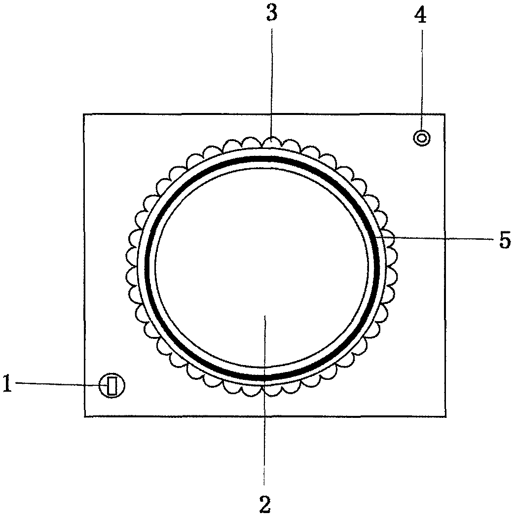
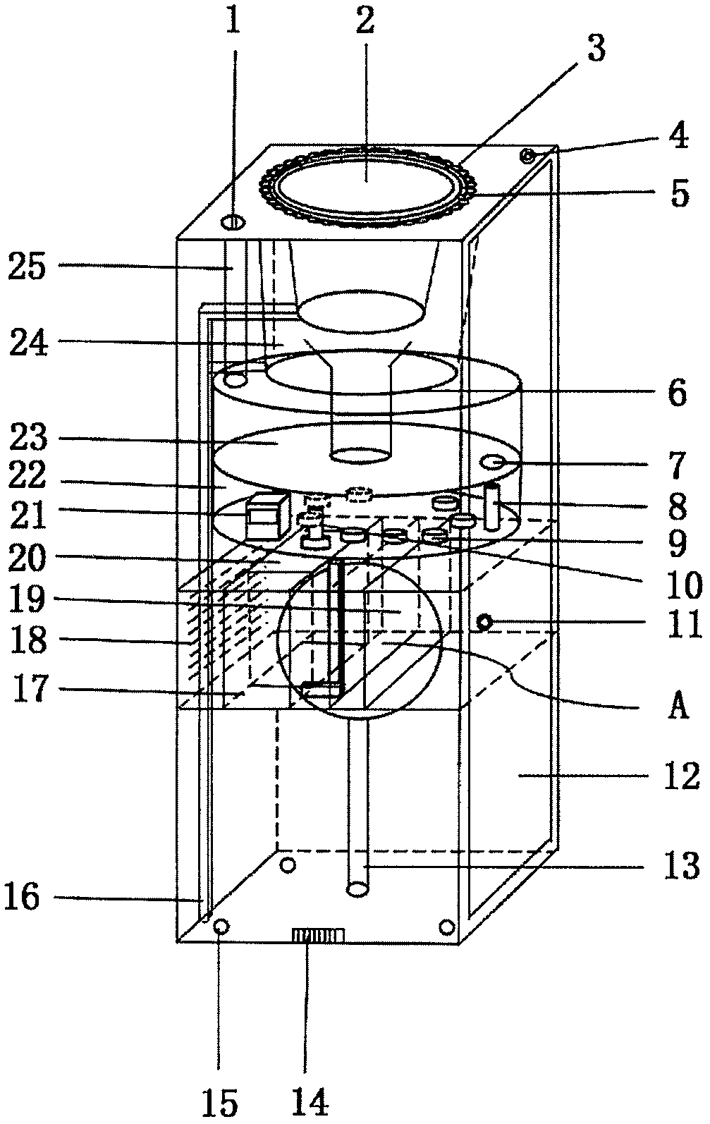
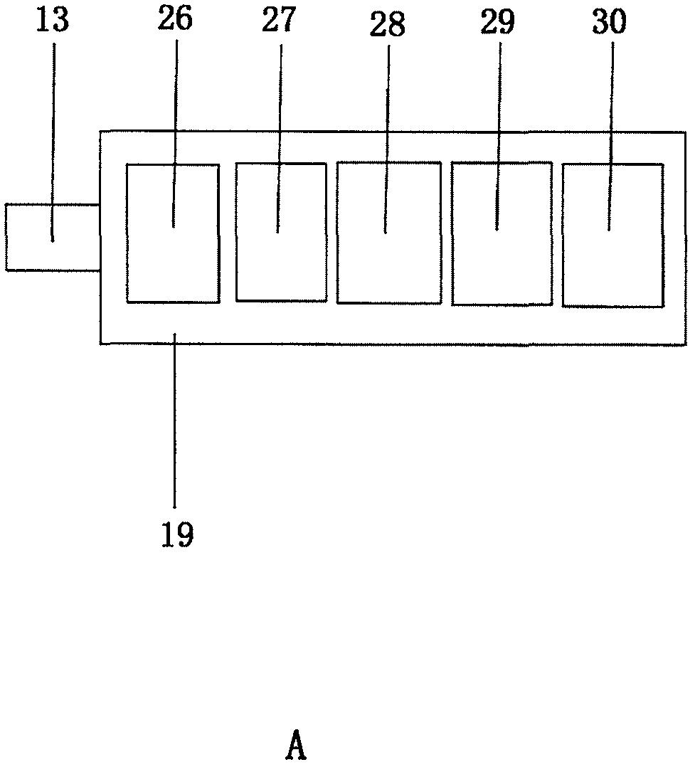
[0023] Such as figure 1 and figure 2 As shown, it is a top schematic diagram and a three-dimensional structure diagram of a flower box type air humidifying device of the present invention. The flower box body is divided into upper and lower parts. The upper part is the flower display area 2 and the lower part is the ultrasonic atomization area 22. The flower display area 2 is provided with a humidity sensor 4, a water injection port 1, and a drainage pipe 16 is provided on the lower side wall of the flower display area to communicate with the outside world. The control box 19 is provided with a control circuit 29 , a signal transmitter 30 , a time controller 28 , a power failure protector 27 and a power supply device 26 . The bottom end of the ultrasonic atomization area 22 is provided with a waterproof fan 20, and the waterproof fan 20 is provided with an air inlet 18 corresponding to the side wall of the flower box body. The ultrasonic atomization area 22 is provided with...

Embodiment 2

[0028] see figure 2 1. The flower box body top flower placement area 2 periphery is provided with LED light bar 5, and LED light bar 5 emits light according to the preset value after power supply device 26 passes through time controller 28 power supply. Improve the city lighting effect and reduce the probability of flower boxes being damaged by vehicles.

Embodiment 3

[0030] The flower box body is divided into a detachable structure, and the side of the flower box body is provided with an inspection door 12, which is convenient for replacing the ultrasonic atomizer 9 and equipment maintenance.


PUM


Abstract

The invention relates to a flower-box-type air humidifier. A flower box body is divided into an upper part and a lower part; the upper part is a flower placement zone, and the lower part is an ultrasonic atomization zone; the lower placement zone is provided with a humidity sensor, a water injection port and mist outlets; a water drainage pipeline is arranged on the lower end side wall of the flower placement zone and communicates with the outside; a control circuit, a signal emitter, a time controller, a power-off protection device and a power supplying device are arranged in a control box; awaterproof fan is arranged on the lower end of the ultrasonic atomization zone; the part, which corresponds to the waterproof fan, of the side wall of the flower box body is provided with an air inlet; the ultrasonic atomization zone is provided with an ultrasonic atomizer head, a floater and a water injection port; the floater inducts water shortage and triggers power-off protection; a water injection pipeline is arranged on the upper end of a water tank of the ultrasonic atomization zone and is connected with the water injection port of the flower placement zone; and a water injection portis formed in the lower end of the water tank of the ultrasonic atomization zone and is connected with an ultrasonic atomization bin. The flower-box-type air humidifier provided by the invention realizes air humidifying, road dust falling, air cooling and air purifying while meeting requirement of urban landscape.

Description

Technical field: [0001] The present invention relates to a kind of flower box, more specifically, it relates to a kind of flower box type air humidifying device. Background technique: [0002] At present, the quality of people's living environment is deteriorating, the air quality is declining, automobile exhaust, industrial dust and other problems, people are paying more and more attention to the living environment, the humidifier industry has a history of more than 20 years in China, after years of market cultivation, product research and development has become more and more more and more mature. But at present, humidifiers are mainly aimed at living spaces and some specific environments. [0003] However, there are problems such as single function and independent setting in the traditional flower box. In the prior art, there are also flower boxes that use atomizing nozzles for atomization, but there are still the following deficiencies: ① the atomizing nozzles are easil...

Claims


Application Information

Patent Timeline
IPC IPC(8): F24F6/12F24F11/61A01G9/02A01G27/00A01G27/02
CPCA01G9/02A01G27/003A01G27/02F24F6/12F24F2221/26Y02B30/70
Inventor 高晟邺
Owner 高晟邺
Why Eureka
Try Eureka