Multi-station automatic workpiece punching method

A multi-station and workpiece technology, applied in the field of stamping, can solve the problems of reducing stamping efficiency and achieve the effect of improving stamping efficiency

Inactive Publication Date: 2018-07-17
应金宝
View PDF10 Cites 6 Cited by
  • Summary
  • Abstract
  • Description
  • Claims
  • Application Information

AI Technical Summary

Problems solved by technology

Especially when the workpiece needs to be continuously stamped in multiple processes, it is usually equipped with multiple stamping equipment, and each equipment completes a stamping process. After the previous stamping process is completed, when entering the next stamping equipment, manual transfer is required. Thereby further reducing the stamping efficiency

Method used


Image

  • Multi-station automatic workpiece punching method

Examples


Embodiment Construction

[0016] The present invention will be further described in detail below in conjunction with the accompanying drawings and embodiments.

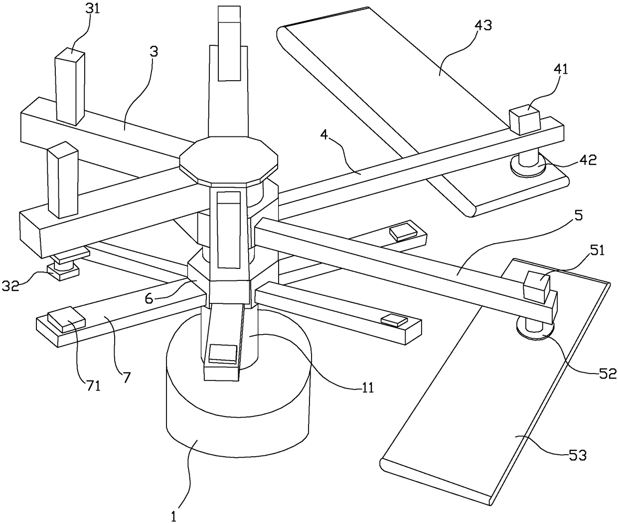
[0017] First, this embodiment describes the multi-station automatic stamping device involved in the multi-station automatic stamping method of the present invention. Such as figure 1 As shown, the multi-station automatic stamping method of the workpiece in this implementation includes a platform 1, a column 11, an upper beam 3, a stamping cylinder 31, an upper die 32, a feeding rod 4, a feeding cylinder 41, a feeding suction cup 42, Discharge rod 5, discharge cylinder 51, discharge suction cup 52, feeding conveyor belt 43, discharge conveyor belt 53, turntable 6, lower beam 6, lower die 61.

[0018] Wherein, there is a column 11 erected on the platform 1, and N upper beams 3 are fixed radially on the top of the column 11, and the outer end of each upper beam 3 is provided with a stamping cylinder 31, and the output end of the stamping cylinde...


PUM


Abstract

The invention discloses a multi-station automatic workpiece punching method. The multi-station automatic workpiece punching method comprises the following steps that a feeding cylinder transfers a to-be-punched workpiece to the position above one of lower dies from a feeding conveying belt; a rotary disc rotates by 360/(N+2) degrees, wherein N is the number of punching times needed for the workpiece, a punching cylinder on a corresponding upper beam drives the corresponding lower die to descend, and one-time punching of the workpiece is achieved; the rotary disc rotates many times, and after rotation every time, upper dies conduct next-time punching on the workpiece; after all the punching procedures are finished for the workpiece, an unloading cylinder transfers the punched workpiece to an unloading conveying belt. The multi-station automatic workpiece punching method is provided, multi-station automatic workpiece punching is achieved, the manual labor intensity is relieved, and the punching efficiency is improved.

Description

technical field [0001] The invention relates to the stamping field, in particular to a multi-station automatic stamping method for workpieces. Background technique [0002] Punching machine is a relatively commonly used industrial production equipment, especially the equipment mainly used for stamping and molding the end of elongated materials such as profiles or steel pipes. Especially when the workpiece needs to be continuously stamped in multiple processes, it is usually equipped with multiple stamping equipment, each equipment completes a stamping process, after completing the previous stamping process, when entering the next stamping equipment, manual transfer is required. Thereby further reducing stamping efficiency. [0003] For this reason, for example, the Chinese invention patent with the existing publication number CN107159803A discloses "Punching Robot Automatic Loading and Unloading System", which includes at least one punching machine, automatic feeding device...

Claims


Application Information

Patent Timeline
Patent Type & Authority Applications(China)
IPC IPC(8): B21D22/08B21D43/12B21D43/18B21D45/06
CPCB21D22/08B21D43/12B21D43/18B21D45/06
Inventor 应金宝
Owner 应金宝
Why Eureka
Try Eureka