A multi-station continuous stamping device

A stamping device and multi-station technology, applied in stamping field, can solve problems such as reducing stamping efficiency, and achieve the effect of continuous stamping process

Active Publication Date: 2019-11-22
浙江赛赛轴承有限公司
View PDF7 Cites 0 Cited by
  • Summary
  • Abstract
  • Description
  • Claims
  • Application Information

AI Technical Summary

Problems solved by technology

Especially when the workpiece needs to be continuously stamped in multiple processes, it is usually equipped with multiple stamping equipment, and each equipment completes a stamping process. After the previous stamping process is completed, when entering the next stamping equipment, manual transfer is required. Thereby further reducing the stamping efficiency

Method used


Image

  • A multi-station continuous stamping device
  • A multi-station continuous stamping device

Examples


Embodiment Construction

[0014] The present invention will be further described in detail below in conjunction with the accompanying drawings and embodiments.

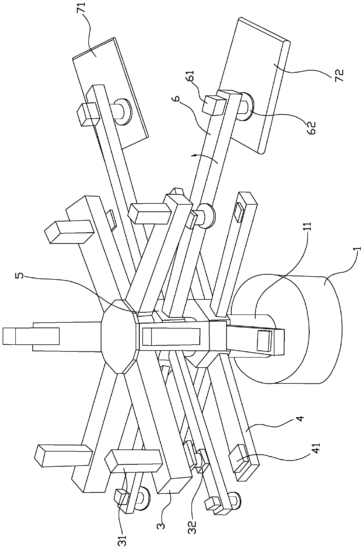
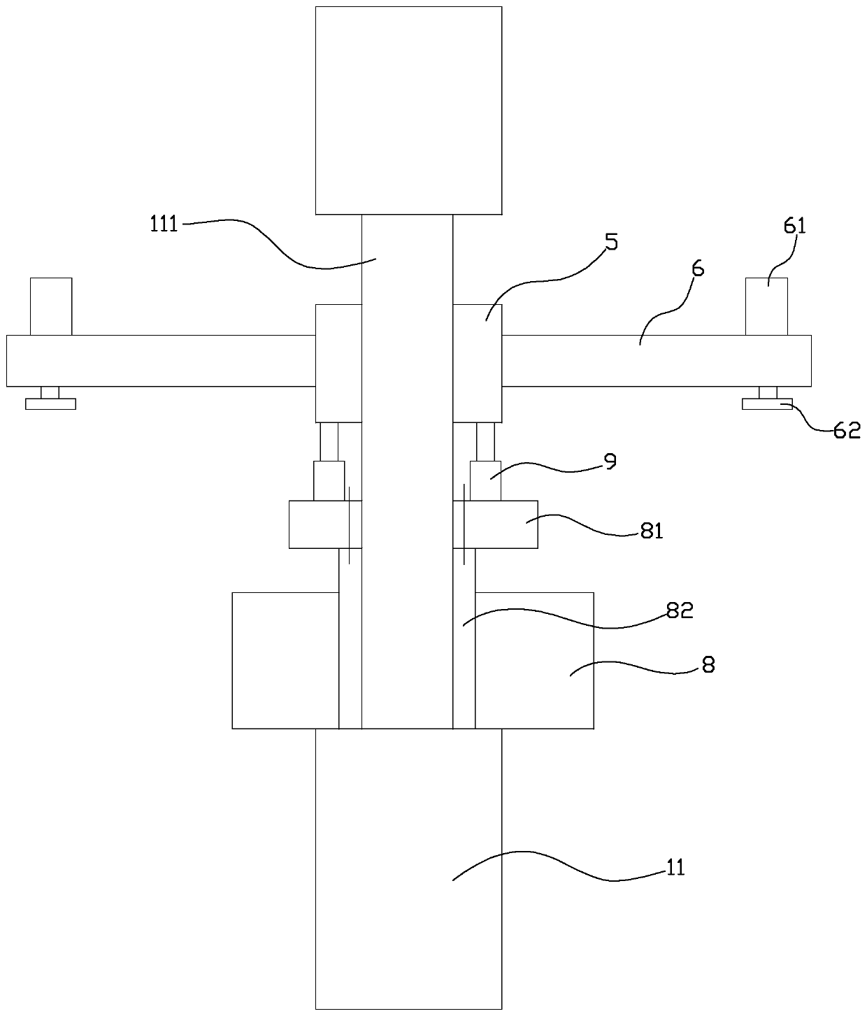
[0015] Such as figure 1 , 2 As shown, the multi-station continuous stamping device in this implementation includes a platform 1, a column 11, an upper beam 3, a stamping cylinder 31, an upper mold 32, a support rod 6, a feeding cylinder 61, a suction cup 62, and a feeding conveyor belt 71 , discharge conveyor belt 72, turntable 5, lower beam 4, lower die 41, hollow motor 8, lifting cylinder 9, fixed plate 81.

[0016] Wherein, a column 11 is erected on the platform 1, and the top of the column 11 is radially fixed with N evenly distributed upper beams 3, N≥2, and the outer end of each upper beam 3 is provided with a stamping cylinder 31, and the output of the stamping cylinder 31 There is an upper die 32 for punching the workpiece once at the end, and a turntable 5 is installed in the middle of the column 11. The turntable 5 rotates intermit...


PUM


Abstract

The invention discloses a device for achieving multi-station continuous punching. The device is characterized by comprising a stand column, N evenly-distributed upper transverse beams are fixedly arranged at the top of the stand column in a radial shape, a punching cylinder is arranged at the outer end of each upper transverse beam, the output end of each punching cylinder is provided with an upper die, a rotary disc is rotationally arranged at the middle portion of the stand column, supporting rods with the quantity the same as that of the upper transverse beams are arranged on the peripheralwall of the rotary disc in the radial shape, each supporting rod is provided with a feeding cylinder, the output end of each feeding cylinder is provided with a sucking disc, a feeding conveying beltis arranged below one supporting rod, a discharging conveying belt is arranged below the supporting rod adjacent to the above supporting rod, lower transverse beams are fixedly arranged at the bottomof the stand column in a radial shape, and each lower transverse beam is provided with a lower die corresponding to the upper die. By means of the device for achieving multi-station continuous punching, multi-station automatic punching of workpieces is achieved, the hand labor strength is reduced, and the punching efficiency is improved.

Description

technical field [0001] The invention relates to the stamping field, in particular to a multi-station continuous stamping device. Background technique [0002] Punching machine is a relatively commonly used industrial production equipment, especially the equipment mainly used for stamping and molding the end of elongated materials such as profiles or steel pipes. Especially when the workpiece needs to be continuously stamped in multiple processes, it is usually equipped with multiple stamping equipment, each equipment completes a stamping process, after completing the previous stamping process, when entering the next stamping equipment, manual transfer is required. Thereby further reducing stamping efficiency. [0003] For this reason, for example, the Chinese invention patent with the existing publication number CN105149473A discloses "A Multi-station Continuous Stamping Device for Workpieces", which includes a plurality of lower stamping dies arranged on the machine platfo...

Claims


Application Information

Patent Timeline
Patent Type & Authority Patents(China)
IPC IPC(8): B21D22/08B21D43/12B21D43/18B21D43/14B21D45/06
CPCB21D22/08B21D43/026B21D43/12B21D43/14B21D43/18B21D45/06
Inventor 应金宝
Owner 浙江赛赛轴承有限公司
Why Eureka
Try Eureka