Automobile roof air channel air-tightness detection device

An air tightness detection and air duct technology, which can be used in liquid/vacuum measurement for liquid tightness, by detecting the appearance of fluid at the leak point, and by measuring the acceleration and deceleration rate of the fluid, etc. Provide detailed reference for the production steps of the air duct, it is impossible to judge that the air-tightness of the air duct of the car canopy is good, and it is impossible to test the air leakage of the air duct of the car canopy, so as to achieve the effect of easy observation.

Inactive Publication Date: 2018-07-17
丹阳市宸泰汽车部件有限公司
View PDF0 Cites 1 Cited by
  • Summary
  • Abstract
  • Description
  • Claims
  • Application Information

AI Technical Summary

Problems solved by technology

[0002] The air-tightness test of the existing car roof air duct uses a blower device to connect the sealed box through the pipeline, connects the anemometer and the barometer to the sealed box, and judges the air tightness of the car roof air duct by the change of the air outlet wind speed and the barometer To provide an improved reference for the production of roof air ducts, but the existing detection devices cannot detect air leaks in the roof air ducts, and cannot provide detailed information on the various production steps of the roof air ducts. reference, and under the condition that the existing detection device itself leaks air, it is impossible to judge whether the air duct of the car roof is well airtight

Method used


Image

  • Automobile roof air channel air-tightness detection device
  • Automobile roof air channel air-tightness detection device
  • Automobile roof air channel air-tightness detection device

Examples


Embodiment Construction

[0019] The following will clearly and completely describe the technical solutions in the embodiments of the present invention with reference to the accompanying drawings in the embodiments of the present invention. Obviously, the described embodiments are only some, not all, embodiments of the present invention.

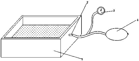
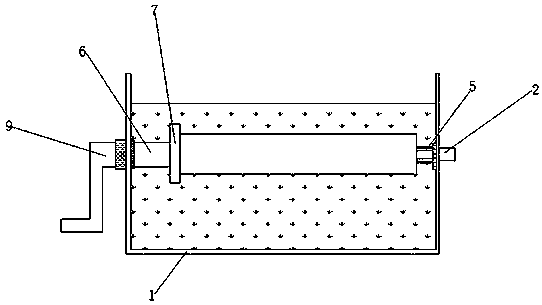
[0020] refer to Figure 1-3 , a kind of airtightness detection device of automobile ceiling air duct, comprises the box body 1 of hollow structure, is provided with clean water in box body 1, is provided with opening on the top of box body 1, and is connected on the side outer wall of box body 1 Intake pipe 2, and the air inlet pipe 2 is connected to the air pressure gauge 3 through the rubber conduit, and the rubber conduit is connected to the rubber tube, and the end of the rubber tube away from the rubber conduit is connected to the pressurized ball 4, and the side of the box body 1 close to the intake pipe 4 The side outer wall is rotatably connected with a conne...


PUM


Abstract

The invention discloses an automobile roof air channel air-tightness detection device, which comprises a hollow-structure box body. The box body is internally provided with clear water. The top portion of the box body is provided with an opening; an outer wall at one side of the box body is connected with an air inlet pipe; the air inlet pipe is connected with an air pressure gauge through a rubber guide pipe; the rubber guide pipe is connected with a rubber pipe; and one end, away from the rubber guide pipe, of the rubber pipe is connected with a pressurization ball. An outer wall at the side, close to the air inlet pipe, of the box body is rotatably connected with a connection pipe; and the connection pipe is connected with the air inlet pipe. An inner wall at one side, away from the connection pipe, of the box body is rotatably connected with a connection rod; and one end, away from the inner wall of the box body, of the connection rod is sleeved by a plug member. The outer wall atthe side, close to the connection rod, of the box body is provided with a groove, and the groove is internally provided with a bearing. The device can test the air-tightness of an automobile roof airchannel, can observe each leakage place of the automobile roof air channel, and provides basis for improvement for production of the automobile roof air channel.

Description

technical field [0001] The invention relates to the technical field of airtightness detection devices, in particular to an airtightness detection device for an automobile roof air duct. Background technique [0002] The air-tightness test of the existing car roof air duct uses the blower device to connect the sealed box through the pipeline, connects the anemometer and the barometer to the sealed box, and judges the air tightness of the car roof air duct by the change of the air outlet wind speed and the barometer To provide an improved reference for the production of roof air ducts, but the existing detection devices cannot detect air leaks in the roof air ducts, and cannot provide detailed information on the various production steps of the roof air ducts. As a reference, and under the condition of air leakage of the existing detection device itself, it is impossible to judge whether the air duct of the car roof is well airtight. Contents of the invention [0003] The pu...

Claims


Application Information

Patent Timeline
Patent Type & Authority Applications(China)
IPC IPC(8): G01M3/26G01M3/06
CPCG01M3/26G01M3/06
Inventor 彭凡
Owner 丹阳市宸泰汽车部件有限公司
Why Eureka
Try Eureka