Diaphragm airtightness detection automation device and use method thereof

A technology of air tightness detection and automatic device, which is applied in the direction of using liquid/vacuum degree for liquid tightness measurement and measuring the acceleration and deceleration rate of fluid, etc., can solve the problem of small detection amount, poor detection effect, inconvenience and intelligence question

Pending Publication Date: 2020-11-17
安徽科博航空装备有限公司
View PDF0 Cites 1 Cited by
  • Summary
  • Abstract
  • Description
  • Claims
  • Application Information

AI Technical Summary

Problems solved by technology

[0003] At present, the detection of diaphragms on the market is not convenient and intelligent enough, the single detection amount is small, and the detection effect is poor

Method used


Image

  • Diaphragm airtightness detection automation device and use method thereof
  • Diaphragm airtightness detection automation device and use method thereof
  • Diaphragm airtightness detection automation device and use method thereof

Examples


Embodiment 1

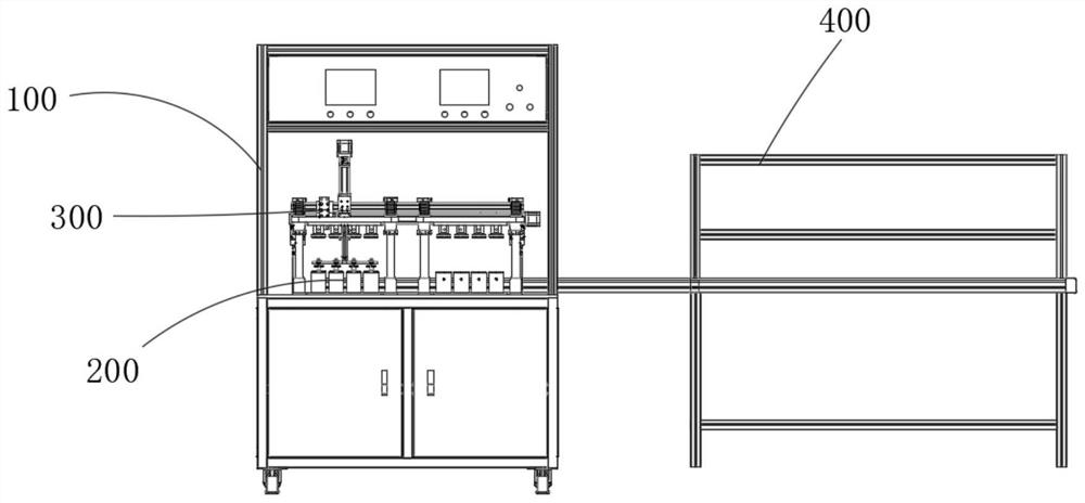
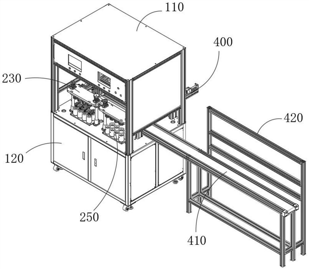
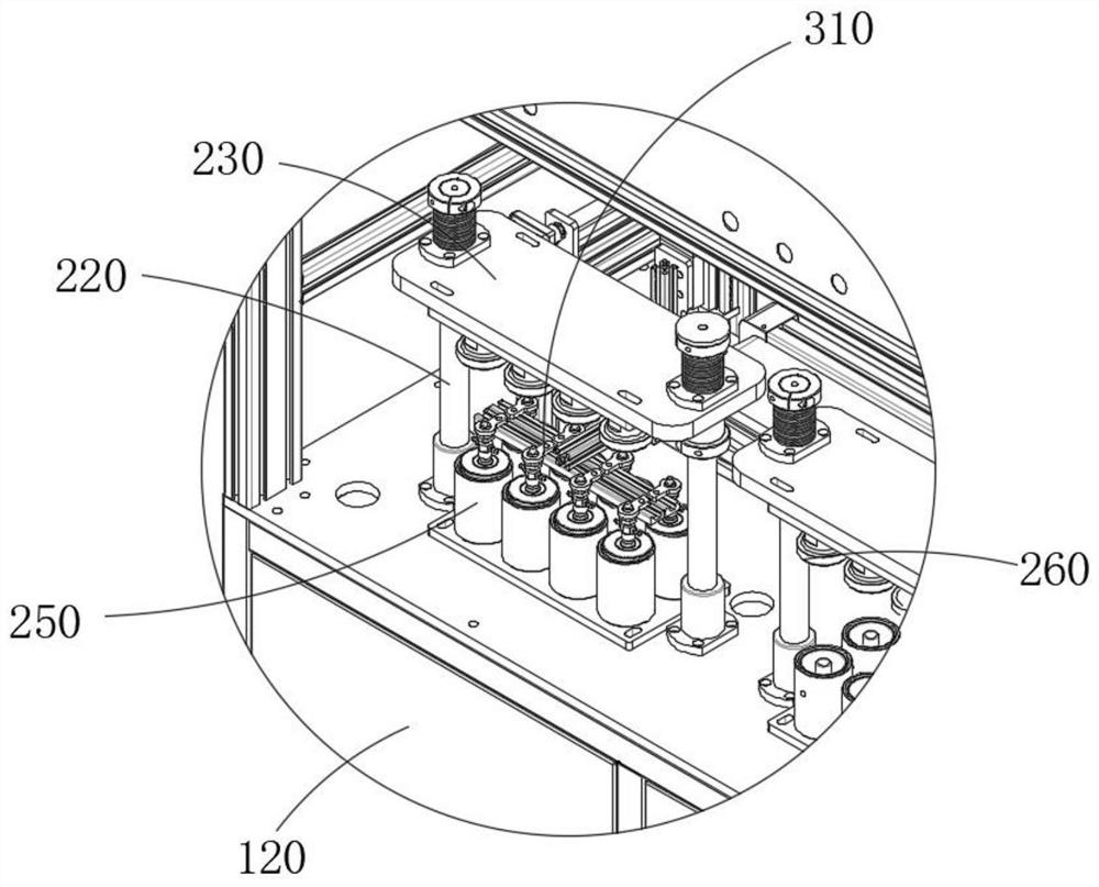
[0039] Refer to attached Figure 1-Figure 6 As shown, a diaphragm airtightness detection automation device of this embodiment includes a frame 100, a positioning tool 200, a detection mechanism 300 and a transmission mechanism 400, and the positioning tool 200 and the detection mechanism 300 are located in the frame 100, and the machine The frame 100 includes an upper frame 110 and a lower platform 120, and the detection mechanism 300 includes a three-axis translation stage 310, a horizontal support 320 and a vacuum suction cup 330, and the three-axis translation stage 310 is installed in the upper frame 110, and the three-axis translation stage 310 is installed with a horizontal Support 320 and vacuum suction cup 330, positioning tool 200 is installed on the table of lower stand 120, and positioning tool 200 comprises cylinder 210, optical axis 220, pressure plate 230, connecting plate 240, lower jig 250 and upper jig 260, and cylinder 210 is installed In the lower platform 1...

Embodiment 2

[0046] Refer to attached Figure 1-Figure 6 As shown, a method for using a diaphragm airtightness detection automation device in this embodiment, the method includes the following steps:

[0047]S100, placing the membrane to be detected on the lower jig 250;

[0048] S200, the upper jig 260 moves downward to press the diaphragm, and vacuumizes the inside of the upper jig 260;

[0049] S300, the gas detection machine detects the air tightness of the diaphragm, and controls the upper fixture 260 to rise;

[0050] S400, the three-axis translation stage 310 drives the vacuum suction cup 330 to absorb the diaphragm, and places it on the conveyor belt 410 or the waste area.

[0051] The specific method of step S300 of this embodiment is that the gas detector vacuumizes the upper fixture 260. If the diaphragm leaks, the pressure in the upper fixture 260 will not change, and the gas detector detects the pressure value to determine whether the diaphragm is Leakage, after the detecti...


PUM


Abstract

The invention belongs to the technical field of detection tools, and relates to a diaphragm airtightness detection automation device and a use method thereof, the diaphragm airtightness detection automation device comprises a rack, a positioning tool, a detection mechanism and a conveying mechanism; the rack comprises an upper frame and a lower frame, the detection mechanism comprises a three-axisdisplacement table, a transverse support and a vacuum sucker, and the three-axis displacement table is installed in the upper frame; a transverse bracket and a vacuum chuck are mounted on the three-axis displacement table; the positioning tool comprises an air cylinder, polished shafts, a pressing plate, a connecting plate, lower jigs and upper jigs; the air cylinder is installed in the lower frame, the connecting plate is arranged on a piston rod of the air cylinder, the two ends of the connecting plate are fixedly connected with the polished shafts, the pressing plate is fixedly arranged atthe tops of the polished shafts, and the multiple upper jigs are arranged at the bottom of the pressing plate. A plurality of lower jigs are arranged at the top of the lower frame, the two sides of the diaphragm are covered with the upper jigs and the lower jigs, just like air holes communicated with the outside are formed in the lower jigs in the upper jigs, vacuumizing operation is further conducted on air in the upper jigs, and then the air tightness of the diaphragm can be detected.

Description

technical field [0001] The invention belongs to the technical field of inspection tools, and more specifically relates to an automatic device for detecting air tightness of a diaphragm and a method for using the same. Background technique [0002] Diaphragms are used for airtight protection in many mechanical parts, so the airtightness of the diaphragm directly affects the airtightness of the entire mechanical parts. [0003] At present, the detection of diaphragms on the market is not convenient and intelligent enough, the single detection amount is small, and the detection effect is poor. Contents of the invention [0004] 1. The technical problem to be solved by the invention [0005] The aim of the present invention is to solve the above-mentioned drawbacks. [0006] 2. Technical solution [0007] In order to achieve the above object, the technical scheme provided by the invention is: [0008] A diaphragm airtightness testing automatic device of the present inventi...

Claims


Application Information

Patent Timeline
Patent Type & Authority Applications(China)
IPC IPC(8): G01M3/26
CPCG01M3/26
Inventor 张管张文轩
Owner 安徽科博航空装备有限公司
Why Eureka
Try Eureka