Method for in-situ blocking and remediating heavy metal contaminated bottom mud

A technology of polluted bottom sludge and remediation method, applied in the direction of sludge detoxification, water pollutants, sludge treatment, etc., can solve the problems of release and secondary pollution, and achieve the effect of preventing release and eliminating environmental risks

Inactive Publication Date: 2018-07-20
中化工程集团环保有限公司
View PDF10 Cites 1 Cited by
  • Summary
  • Abstract
  • Description
  • Claims
  • Application Information

AI Technical Summary

Problems solved by technology

Some projects will landfill the contaminated sediment, and the heavy metals in the sludge will also be released into the leachate after landfill, posing a risk of secondary pollution

Method used


Image

  • Method for in-situ blocking and remediating heavy metal contaminated bottom mud

Examples


specific Embodiment approach

[0017] The in-situ barrier repair method of heavy metal polluted bottom mud of the present invention, its preferred embodiment is:

[0018] Include steps:

[0019] A. Division of treatment units and setting of temporary storage pools: According to the sediment thickness and heavy metal content of the target restoration area of ​​the watershed to be restored, and the geographical distribution of the restoration area, the area to be repaired is divided into several unit areas. Set up temporary storage tanks for sediment disposal according to the amount of sludge to be treated in the divided unit area;

[0020] B. Transfer and stabilization of bottom sludge: transfer the bottom sludge in the unit area to the temporary storage tank, and add stabilizing agents to the sludge in the tank to achieve passivation of heavy metals in the sludge;

[0021] C. Laying of the bottom isolation mold bag: Lay the isolation layer to the bottom of the unit area after cleaning the bottom mud;

[0...

specific Embodiment

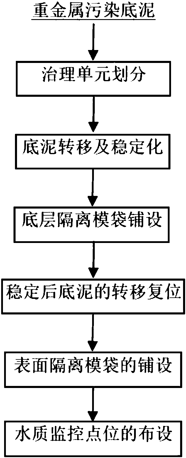
[0034] Such as figure 1 shown, including the following steps:

[0035] (1) Governance unit division and temporary storage pool settings:

[0036] According to the terrain characteristics of the area to be treated, the grid layout method is used to divide the area to be treated into governance units. The distance between two adjacent layout points is generally 30m-50m. The bottom mud excavation depth of the treatment unit is determined according to the heavy metal content in the bottom mud, generally 2m-3m. The temporary storage tank is a temporary structure built, and its volume is about 1.2-1.3 times the amount of sediment to be excavated in the treatment unit. The temporary storage tank is lined with HDPE anti-seepage membrane, and the thickness of the anti-seepage membrane is not less than 2mm.

[0037] (2) Sediment transfer and stabilization

[0038] Gradually excavate the sediment in the treatment unit by machinery, transfer it to a mechanical agitator after excavation...


PUM

PropertyMeasurementUnit
thicknessaaaaaaaaaa
thicknessaaaaaaaaaa
thicknessaaaaaaaaaa

Abstract

The invention discloses a method for in-situ blocking and remediating heavy metal contaminated bottom mud. The method comprises the steps of dividing an area to be remediated into mesh units, arranging a sludge temporary storage tank, transferring the contaminated bottom mud in the mesh unit area into the temporary storage tank, fully mixing the contaminated bottom mud and a heavy metal stabilizing reagent in the temporary storage tank for reacting, and then returning to the original mesh unit area. Heavy metal diffusion blocking layers are arranged on the bottom part and the upper part of theoriginal mesh unit area, so that trace heavy metals released from the bottom mud are prevented from diffusing and migrating into underwater and surface water. Compared with traditional treatment technologies such as using the bottom mud for manufacturing building materials, and landfilling with the bottom mud, the method is beneficial to the effective inhibition of the dissolving and the releasing of the heavy metals in the bottom mud and the prevention of secondary pollution of the bottom mud, avoids the problem that the sludge is finally difficult to treat, has the characteristics of high treatment efficiency, investment and operation cost reduction, and the like, is suitable for remediating the heavy metal contaminated bottom mud of rivers, lakes and the like, and has higher popularization and application value.

Description

technical field [0001] The invention relates to an in-situ restoration technology for rivers, lakes, reservoirs and the like contaminated by heavy metals, in particular to an in-situ barrier restoration method for heavy metal-contaminated sediments. Background technique [0002] At present, the rapid development of "heavy" industries such as heavy non-ferrous metal mining and smelting, chemical raw materials and chemical manufacturing, metal surface treatment and heat treatment processing, and lead-containing battery manufacturing is accompanied by the generation of heavy metal pollutants environmental issues such as emissions. After the heavy metals enter the environmental water body with the wastewater, most of them are rapidly transferred from the water phase to the solid phase under physical and chemical effects such as physical precipitation, chemical adsorption, and surface complexation, and are deposited in the sediment, resulting in a large number of natural water bo...

Claims


Application Information

Patent Timeline
Patent Type & Authority Applications(China)
IPC IPC(8): C02F11/00C02F101/20
CPCC02F11/004C02F2101/20
Inventor 胡建龙李志刚吴志明刘书娟
Owner 中化工程集团环保有限公司
Why Eureka
Try Eureka