Bending machine

The technology of a bending machine and bending mechanism is applied in the field of bending machines to achieve the effects of reducing production costs, simplifying the structure, and being convenient to use

Pending Publication Date: 2018-07-24
OMS MASCH CO LTD
View PDF9 Cites 2 Cited by
  • Summary
  • Abstract
  • Description
  • Claims
  • Application Information

AI Technical Summary

Problems solved by technology

[0003] The purpose of the present invention is to provide a bending machine to solve the problem in the prior art that an additional follower plate driving mechanism needs to be configured

Method used


Image

  • Bending machine
  • Bending machine
  • Bending machine

Examples


Embodiment Construction

[0019] Below, in conjunction with accompanying drawing and specific embodiment, the present invention is described further:

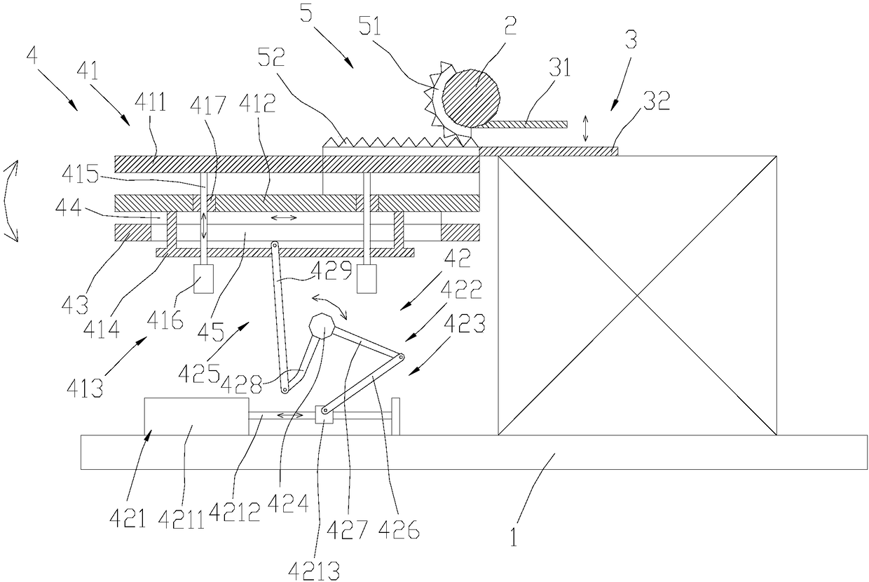
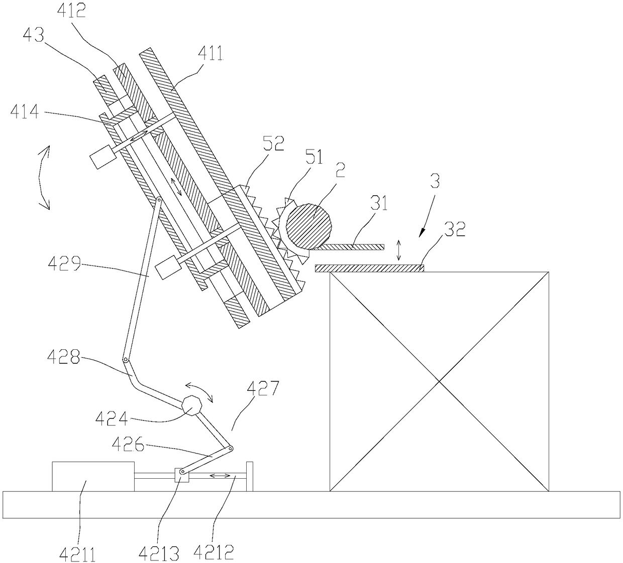
[0020] refer to figure 1 and figure 2 , a bending machine, comprising a base 1, the base 1 is provided with a turning roller 2, one side of the turning roller 2 is provided with a clamping mechanism 3, and the other side is provided with a bending mechanism 4, the folding The bending mechanism 4 can be bent around the turning roller 2, the bending mechanism 4 is provided with a follower plate 41, and a linkage mechanism 5 is arranged between the turning roller 2 and the follower plate 41, when the When the bending mechanism 4 bends around the rotating roller 2, the linkage mechanism 5 drives the follower plate 41 to move in linkage, so that the follower plate 41 moves with the workpiece.

[0021] Through the above-mentioned structural arrangement, when in use, the clamping mechanism clamps the workpiece, and the bending mechanism drives the workpiece...


PUM


Abstract

The invention discloses a bending machine which comprises a base. A rotary roller is arranged on the base; a clamping mechanism is arranged on one side of the rotary roller; a bending mechanism is arranged on the other side of the rotary roller and can bend around the rotary roller; a follower plate is arranged on the bending mechanism; a linkage mechanism is arranged between the rotary roller andthe follower plate; and when the bending mechanism bends around the rotary roller, the linkage mechanism drives the follower plate to link, so that the follower plate moves along with a workpiece. Through the structure arrangement, when in use, the clamping mechanism clamps the workpiece, and the bending mechanism drives the workpiece to bend around the rotary roller so as to bend the workpiece,so that the bending machine is simple in structure and convenient to use. The bending mechanism bends around the rotary roller, the linkage mechanism is arranged between the rotary roller and the follower plate, and under the action of the linkage mechanism, the follower plate on the bending mechanism moves along with the workpiece, so that the workpiece is further protected; and in addition, no extra drive mechanism is needed to be arranged as a power source of the follower plate, so that the structure of the bending machine is simplified, and the production cost is reduced.

Description

technical field [0001] The invention relates to the field of bending equipment, in particular to a bending machine. Background technique [0002] With the development of technology, the application of devices such as heat exchangers is becoming more and more extensive. Heat exchangers generally require a bending machine to be bent and formed. At present, the bending machines on the market generally include a rotating roller, a follower plate and a clamping mechanism, and the workpiece is bent and formed through the cooperation of the three. In the prior art, the follower plate requires an additional driving mechanism to drive the follower plate to move with the workpiece. This leads to a complex structure of the bending machine and high production costs. Therefore, it is necessary to provide a bending machine with simple structure and low production cost. Contents of the invention [0003] The purpose of the present invention is to provide a bending machine to solve th...

Claims


Application Information

Patent Timeline
Patent Type & Authority Applications(China)
IPC IPC(8): B21D7/024
CPCB21D7/024
Inventor 龙晓斌
Owner OMS MASCH CO LTD
Why Eureka
Try Eureka