
Automobile part punching mechanism with powerful scrap iron suction and discharge functions

A technology for auto parts and iron filings, applied in cleaning methods and utensils, cleaning methods using gas flow, chemical instruments and methods, etc. Conducive to suction and discharge, improving processing efficiency and quality of finished products

Pending Publication Date: 2018-07-27
HUZHOU IRON FORCE METAL PROD
View PDF16 Cites 0 Cited by
  • Summary
  • Abstract
  • Description
  • Claims
  • Application Information

AI Technical Summary

Problems solved by technology

At the same time, the scrap iron chips formed after punching will be scattered around the processing mechanism, causing pollution to the working environment, and in severe cases will affect the processing of the workpiece

Method used


Image

  • Automobile part punching mechanism with powerful scrap iron suction and discharge functions
  • Automobile part punching mechanism with powerful scrap iron suction and discharge functions
  • Automobile part punching mechanism with powerful scrap iron suction and discharge functions

Examples


Embodiment Construction

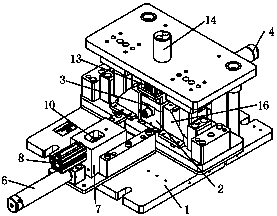
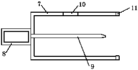
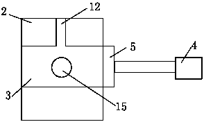
[0012] Combine below Figure 1 to Figure 3 Specific description embodiment:

[0013] The auto parts punching mechanism includes a base 1, the base 1 is provided with a hole die 2, and the hole die 2 is provided with a through hole 3 for placing a workpiece, and the through hole 3 One end is provided with a feed cylinder 4, and the output end of the feed cylinder 4 is provided with a seal 5 that seals one end of the through hole; the base 1 is provided with a stamping cylinder 6, and the output end of the stamping cylinder 6 The side punching sleeve 7 and the side punching motor 8 are arranged on the top, the side punching motor 8 is connected with the side punching head 9, the side punching head 9 is arranged in the side punching sleeve 7, the top of the side punching sleeve 7 is provided with a suction port 10, and the side punching An annular elastic pressing piece 11 matching the through hole is arranged on the sleeve at one end close to the through hole, and the side punc...


PUM


Abstract

The invention belongs to the technical field of automobile part punching tools and particularly relates to an automobile part punching mechanism with powerful scrap iron suction and discharge functions. The automobile part punching mechanism with powerful scrap iron suction and discharge functions comprises a base, wherein a hole pressing die is arranged on the base, a through hole capable of accommodating a machined part is formed in the hole pressing die, and a lower punch is arranged in an upper hole and punches the machined part under the action of a charger and a lower punching cylinder;a scrap discharge port is formed in the position, close to the upper hole, of the side of the hole pressing die. The automobile part punching mechanism with powerful scrap iron suction and discharge functions has the benefits as follows: 2 holes can be simultaneously machined once, so that punching of the machined part can be performed once, scrap iron formed during machining can be automaticallysucked and discharged, and the machining efficiency is improved.

Description

technical field [0001] The invention belongs to the technical field of punching tools for auto parts, in particular to a punching mechanism for auto parts with strong suction and discharge of iron filings. Background technique [0002] At present, for the punching of auto parts, the bottom punching mode is generally adopted, that is, the punch is on the top. When punching, the punch punches from top to bottom, usually one hole at a time. After punching a hole, manually adjust the position of the workpiece for the second punching, so if a workpiece needs to be punched with more than 2 holes, punch once, and then adjust the position and punch once, which requires continuous manual adjustment . At the same time, the scrap iron chips formed after punching will be scattered around the processing mechanism, causing pollution to the working environment, and will affect the processing of the workpiece in severe cases. Contents of the invention [0003] The purpose of the present...

Claims


Application Information

Patent Timeline
IPC IPC(8): B21D28/24B08B5/04
CPCB08B5/04B21D28/24
Inventor 潘智平时慧丽高建中张国平汪洋曹象炜
Owner HUZHOU IRON FORCE METAL PROD
Learn More