
Internal riveting mechanism

A technology of riveting mechanism and riveting head, which is applied in the direction of metal processing equipment, forming tools, manufacturing tools, etc., can solve problems such as riveting parts that cannot be riveted, and achieve the effect of large locking force, strong integrity, and easy popularization and application

Pending Publication Date: 2018-07-27
无锡微研中佳精机科技有限公司
View PDF11 Cites 2 Cited by
  • Summary
  • Abstract
  • Description
  • Claims
  • Application Information

AI Technical Summary

Problems solved by technology

[0003] Aiming at the problems existing in the prior art, the present invention provides an internal riveting mechanism, which solves the technical problem that the riveting mechanism in the prior art cannot perform riveting on riveting parts whose riveting point is in the concave part of the product

Method used


Image

  • Internal riveting mechanism
  • Internal riveting mechanism
  • Internal riveting mechanism

Examples


Embodiment Construction

[0019] The specific embodiments of the present invention will be further described below in conjunction with the accompanying drawings.

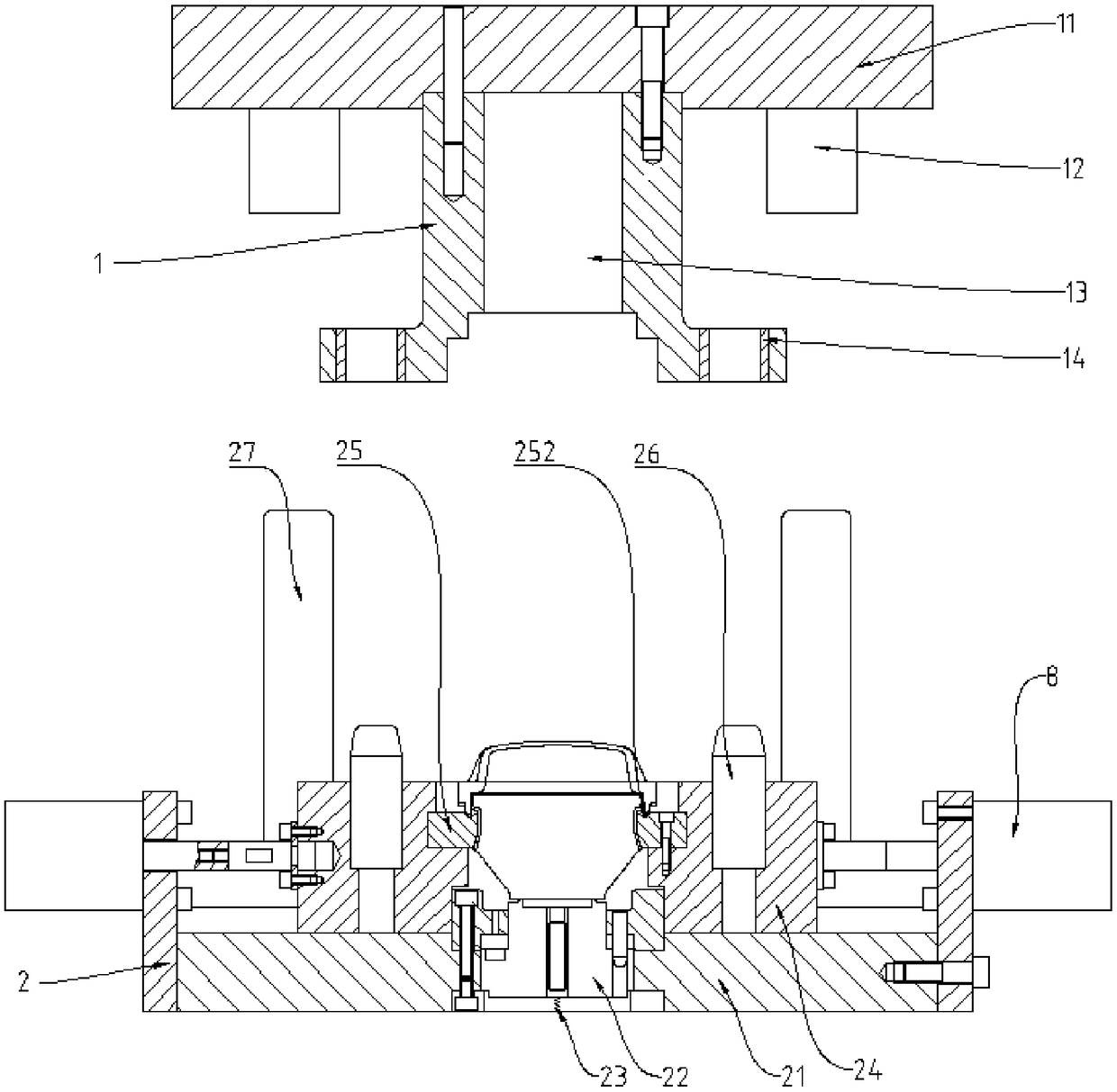
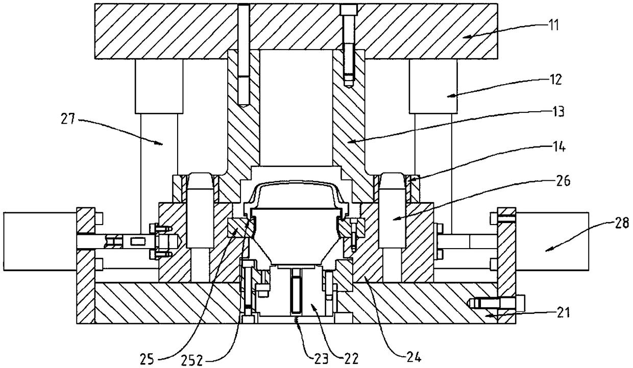
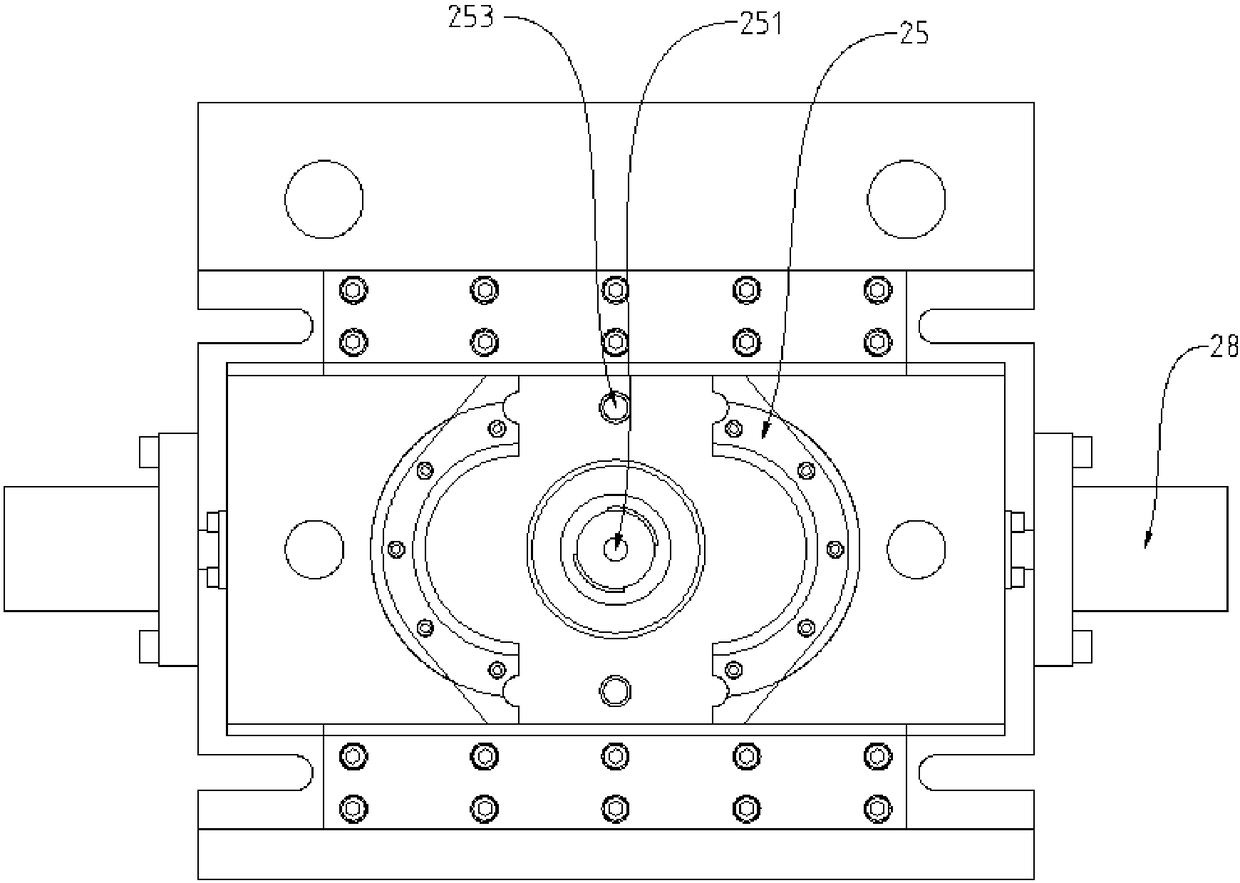
[0020] The technical scheme adopted in the present invention is: as Figure 1 to Figure 5 As shown, a kind of inner riveting mechanism, it comprises upper mold structure 1 and lower mold structure 2, and its upper mold structure 1 comprises upper mold plate 11, and the two sides below upper mold plate 11 are symmetrically arranged with outer guide sleeve 12, and described outer guide sleeve 12 A pressure block 13 is arranged in the middle of the guide sleeve 12, and the shape of the pressure block 13 is a few characters, and the two ends of the pressure block 13 are provided with locking sleeves 14, and the lower mold structure 2 includes a lower template 21. A lower top block 22 is arranged in the middle of the lower template 21, and the lower top block 22 is embedded in the inside of the lower template 21. The lower part of the lower top b...


PUM


Abstract

The invention discloses an internal riveting mechanism. The mechanism comprises an upper die structure and a lower die structure, wherein the upper die structure comprises an upper die plate, outer guide sleeves are symmetrically arranged on the two sides below the upper die plate, pressing blocks are arranged in the middles of the outer guide sleeves, each pressing block is in a capital omega shape, the two ends of the capital omega shape of each pressing block are provided with locking sleeves, the lower die structure comprises a lower die plate, a lower ejection block is arranged in the middle of the lower die plate, the lower ejection block is embedded into the lower die plate, the lower part of the lower ejection block is connected with the lower die plate through a spring, side pushing blocks are arranged on the two sides of the lower ejection block, riveting heads are symmetrically arranged at the positions, opposite to the central axis of the lower ejection block, of the innerside faces of the side pushing blocks on the two sides, locking guide columns are arranged in the middles of the side pushing blocks on the two sides, outer guide columns matched with the outer guidesleeves are arranged above the side pushing blocks on the two sides, and side pushing air cylinders are arranged on the outer side surfaces of the side pushing blocks on the two sides. According to the mechanism, a riveting part with the riveting point at a sunken part of a product is riveted, the overall performance is high, the locking force is large, the structure is stable, popularization andapplication are facilitated.

Description

technical field [0001] The invention relates to a riveting mechanism, in particular to an internal riveting mechanism for riveting a riveted part whose riveting point is in a product depression. Background technique [0002] In the prior art, in the conventional riveting structure, the riveting part of the part is exposed on the outer ring of the part, which can be realized by pushing sideways or pressing down. As for the riveting parts whose riveting point is set in the concave part of the product, when the conventional riveting mechanism is riveting, the structure of the riveting mechanism for side pushing and overall pressing down has no room for movement, which is likely to cause difficulty in forming. Contents of the invention [0003] Aiming at the problems existing in the prior art, the present invention provides an internal riveting mechanism, which solves the technical problem that the riveting mechanism in the prior art cannot perform riveting on riveting parts w...

Claims


Application Information

Patent Timeline
Patent Type & Authority Applications(China)
IPC IPC(8): B21D39/00B21D37/10B21D37/12
CPCB21D37/10B21D37/12B21D39/00
Inventor 张欣
Owner 无锡微研中佳精机科技有限公司
Learn More