
Spoiler system for a vehicle

A technology of spoiler and vehicle, applied in the field of spoiler system

Active Publication Date: 2018-08-03
DR ING H C F PORSCHE AG
View PDF8 Cites 0 Cited by
  • Summary
  • Abstract
  • Description
  • Claims
  • Application Information

AI Technical Summary

Problems solved by technology

[0003] The known solution has the disadvantage that an open gap is formed between the spoiler body and the spoiler receptacle, especially during the movement from the retracted position to at least one extended position

Method used


Image

  • Spoiler system for a vehicle
  • Spoiler system for a vehicle
  • Spoiler system for a vehicle

Examples


Embodiment Construction

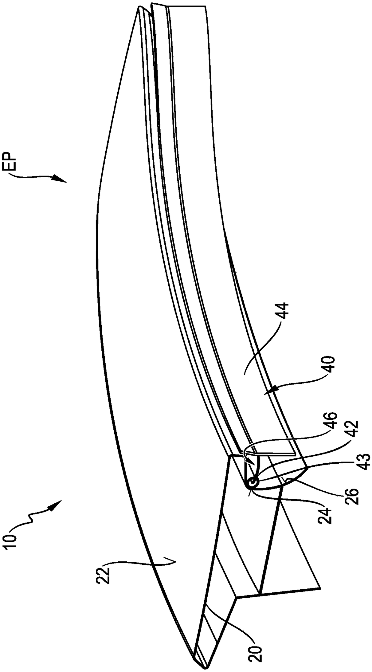
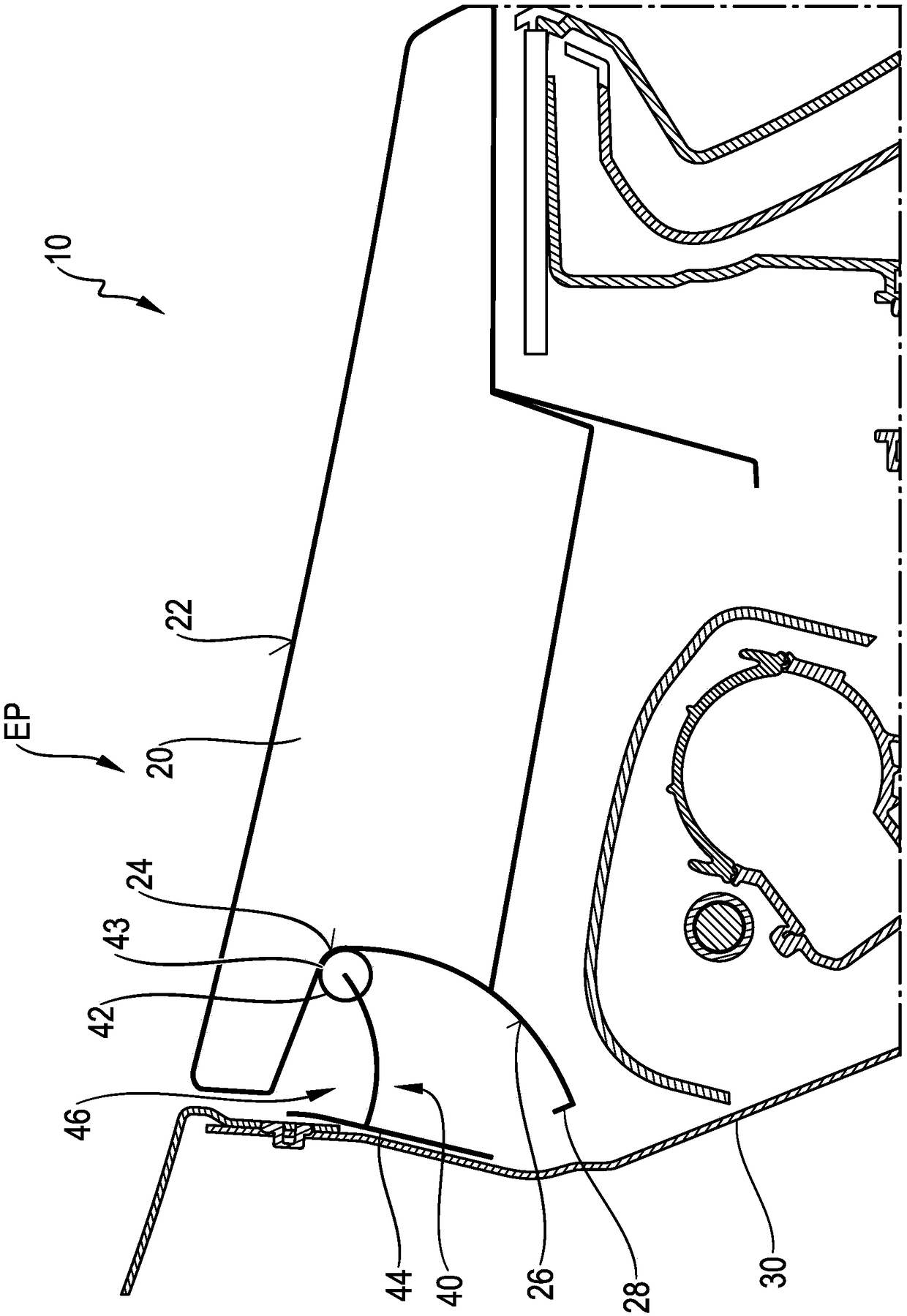
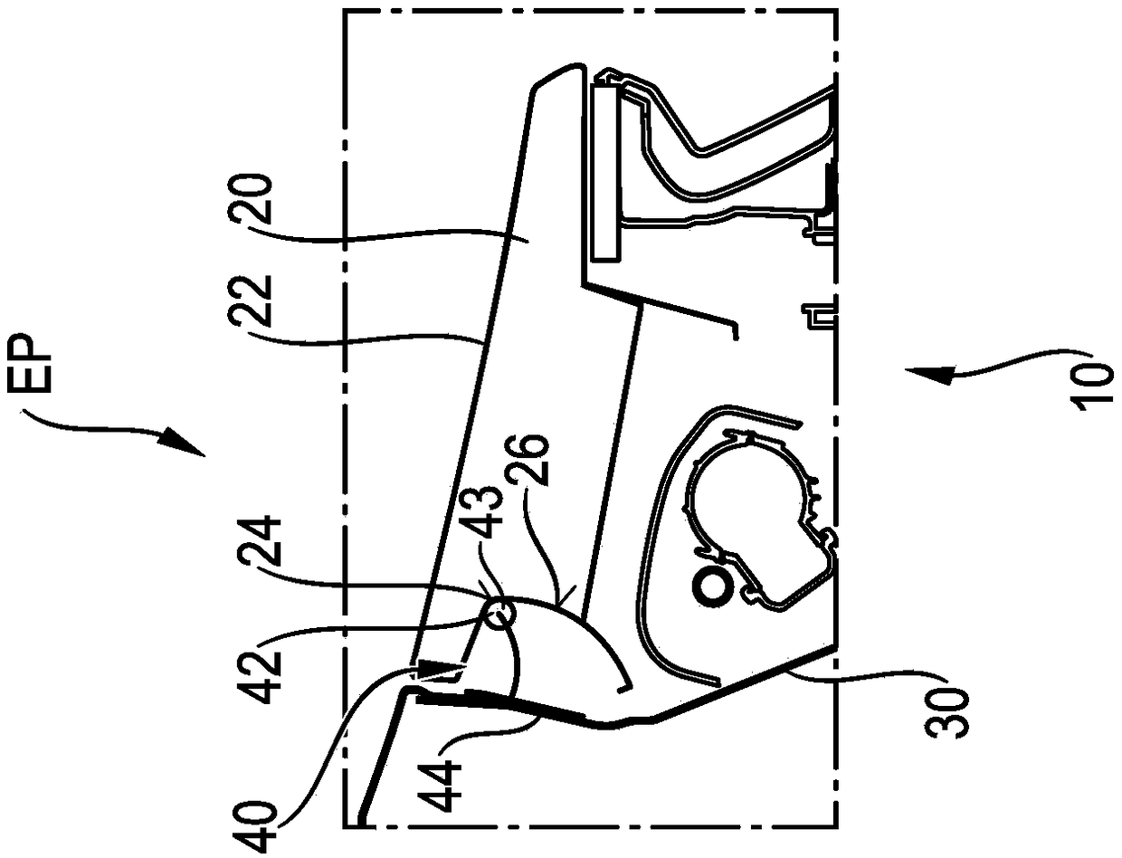
[0047] Such as figure 1 As shown, the spoiler system 10 according to the invention is formed in particular by the combination of the spoiler body 20 and the sealing device 40 . Here, the spoiler body 20 is equipped with an aerodynamically effective spoiler surface 22 which comes into direct contact with the air flow around the vehicle and positively influences it in a desired manner. figure 1 A retracted position EP is shown here in which this influence of the spoiler surface 22 is minimized and the spoiler surface 22 in particular merges into the abutment surface of the vehicle. Here it can already be clearly seen how the sealing device 40 ensures a sealing function below the spoiler body 20 of the spoiler system 10 . Specific reference figure 2 This sealing function is explained in more detail.

[0048] figure 2 A section through the spoiler system 10 is shown and here it can be clearly seen which technical components are located below the spoiler surface 22 of the spo...


PUM


Abstract

A spoiler system (10) for a vehicle includes a spoiler body (20) having a spoiler surface for influencing an air flow around the vehicle. The spoiler body is movably mounted on a spoiler receptacle (30) between a retracted position (EP), in which the spoiler body (20) is received at least partially in the spoiler receptacle (30) and an extended position (AP) in which the spoiler body (20) is extended at least partially out of the spoiler receptacle (30). The spoiler receptacle (30) has a sealing device (40) with a seal (42) configured to provide sealing between the sealing device (40) and a sealing surface (24) of the spoiler body (20) during an extension movement of the spoiler body (20) from the retracted position (EP) into the extended position (AP).

Description

technical field [0001] The invention relates to a spoiler system for a vehicle and to a method for moving a spoiler body of the spoiler system. Background technique [0002] It is known that vehicles should be equipped with spoiler systems in order to positively influence the air flow around the vehicle. In addition to front spoilers, side spoilers or bottom spoilers, rear spoilers are especially known in this respect. It is also known that, in sports vehicles, these spoiler systems are equipped with a spoiler body that is movably mounted between different positions. This relates in particular to different driving situations or different speed situations. During normal driving operation, in order to improve the drag value of the vehicle, the spoiler body can be placed in a retracted position which does not affect or only slightly affects the air flow around the vehicle. However, if high downforce is desired (eg during fast cornering), an extended position can be chosen th...

Claims


Application Information

Patent Timeline
Patent Type & Authority Applications(China)
IPC IPC(8): B62D35/00B60R13/07
CPCB60R13/07B62D35/00Y02T10/82B62D35/007B62D37/02
Inventor F·赫尔曼S·科利特
Owner DR ING H C F PORSCHE AG
Learn More