Supercharge Your Innovation With Domain-Expert AI Agents!

A Pressure Balanced Expansion Joint Based on End Face Sliding Seal Compensation Technology

A sliding seal and expansion joint technology, which is applied to expansion compensation devices, pipe components, mechanical equipment, etc. for pipelines, can solve the problems of uneconomical, harsh end flange force, etc., to improve the force and increase the lateral Displacement compensation capability, effect of thinning design

Active Publication Date: 2020-03-31
LUOYANG SUNRUI SPECIAL EQUIP
View PDF5 Cites 0 Cited by
  • Summary
  • Abstract
  • Description
  • Claims
  • Application Information

AI Technical Summary

Problems solved by technology

The straight pipe pressure balanced expansion joint is a constrained expansion joint. When the sealing method of a sliding seal type expansion joint is directly applied to the straight pipe pressure balanced expansion joint, the connection between the end flange and the sliding flange at this time belongs to In a typical flange connection structure, since the constrained expansion joint is installed on a pipeline without a fixed support, when the direction of the pipeline changes, the axial thrust caused by the pressure acting on the elbow needs to be borne by the flange bolts, and the bolts also It is necessary to provide the sealing pretightening force of the O-ring. The force of the end flange of this structure is harsh, and the flange needs to be thicker to meet the sliding and sealing requirements. Therefore, this sliding sealing structure is applied to the straight pipe pressure balance type There are uneconomical disadvantages when the expansion joint is installed

Method used


Image

  • A Pressure Balanced Expansion Joint Based on End Face Sliding Seal Compensation Technology
  • A Pressure Balanced Expansion Joint Based on End Face Sliding Seal Compensation Technology
  • A Pressure Balanced Expansion Joint Based on End Face Sliding Seal Compensation Technology

Examples


Embodiment 1

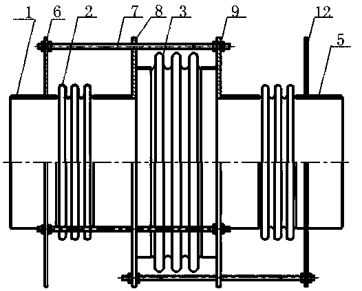
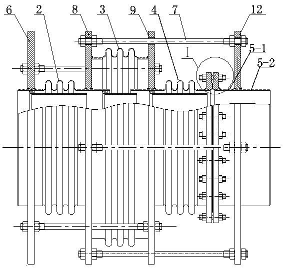
[0022] Such as figure 1 The shown pressure balance expansion joint adopts end face sliding seal compensation technology, its main structure is consistent with the straight pipe pressure balance type expansion joint in GB / T12777, the end face sliding seal compensation structure is added, and the tie rod and end Plate I and end plate II are connected according to the diagram. Such as figure 2 shown in figure 1 Based on the improvement, the end plate II12 and the outlet pipe 5 form an external rigid connection structure through the tie rod 7 and the intermediate pipe assembly I8. A new end flange B11 is added to the outlet pipe 5 as a sliding flange, and the end flange A10, sliding flanges, flange bolts 14, flange gaskets 18, sliding anti-friction gaskets 20, sliding washers 13 and flange nuts 15 form the end face sliding seal compensation structure, which is located in the external rigid connection structure Inside, the bolt hole B on the sliding flange reserves a transverse...

Embodiment 2

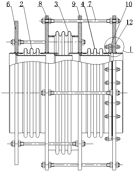
[0024] Such as image 3 A pressure-balanced expansion joint II using end-face sliding seal compensation technology is shown. This structure will image 3 The end plate II of the pressure-balanced expansion joint shown is used as the end flange B, which can shorten the installation space and save parts, and other structures are the same as those in Embodiment 1.


PUM


Abstract

A pressure-balanced expansion joint based on end-face sliding seal compensation technology. The expansion joint includes inlet-end pipes, working bellows I, balance bellows, working bellows II, and outlet-end pipes connected in sequence, as well as multiple sets of tie rod structures. The structure consists of end plate I fixed on the inlet pipe, intermediate pipe assembly I and intermediate pipe assembly II arranged on both sides of the balance bellows, end plate II fixed on the outlet pipe and tie rods. The end-face sliding seal compensation structure is provided on the outlet pipe between the end plate II and the working bellows II. The end flange B on the pipe B, the sliding washer, the flange seal, the flange bolt and the flange nut, this technology improves the lateral displacement compensation ability of the pressure balance expansion joint, and at the same time reduces the stress of the end flange used for the end sliding seal. The flange realizes the thinning design, which reduces the cost of the flange.

Description

technical field [0001] The invention belongs to the technical field of sealing, in particular to a pressure-balanced expansion joint based on end-face sliding sealing compensation technology. Background technique [0002] my country's expansion joint standard GB / T12777 general technical conditions for metal bellows expansion joints defines straight pipe pressure balanced expansion joints as: two working bellows located at both ends and a balanced bellows located in the middle, tie rods and end plates, etc. Composed of structural parts, it is mainly used for expansion joints that absorb axial displacement and can balance the pressure thrust of bellows. In order to increase the lateral displacement compensation capability of the straight pipe pressure balance type expansion joint, CN201520791414.0 straight pipe pressure balance type compensator is designed as a compound bellows for one of the working bellows, and the compound bellows can increase the lateral displacement by con...

Claims


Application Information

Patent Timeline
Patent Type & Authority Patents(China)
IPC IPC(8): F16L51/03
CPCF16L51/03
Inventor 闫廷来李世乾闫保和王伟兵张道伟
Owner LUOYANG SUNRUI SPECIAL EQUIP
Features
  • R&D
  • Intellectual Property
  • Life Sciences
  • Materials
  • Tech Scout
  • Unparalleled Data Quality
  • Higher Quality Content
  • 60% Fewer Hallucinations
Learn More