Supercharge Your Innovation With Domain-Expert AI Agents!

Electrical connector system with enhanced terminal retention beam

An electrical connector system and connector technology, applied in the direction of connection, two-part connection device, parts of the connection device, etc., can solve the problem of unintentional disengagement of the flexible locking member

Active Publication Date: 2019-11-01
DELPHI TECH INC
View PDF13 Cites 0 Cited by
  • Summary
  • Abstract
  • Description
  • Claims
  • Application Information

AI Technical Summary

Problems solved by technology

Unfortunately, the flexible locking member can be inadvertently disengaged, allowing the terminal to be removed from the connector body

Method used


Image

  • Electrical connector system with enhanced terminal retention beam
  • Electrical connector system with enhanced terminal retention beam
  • Electrical connector system with enhanced terminal retention beam

Examples


Embodiment Construction

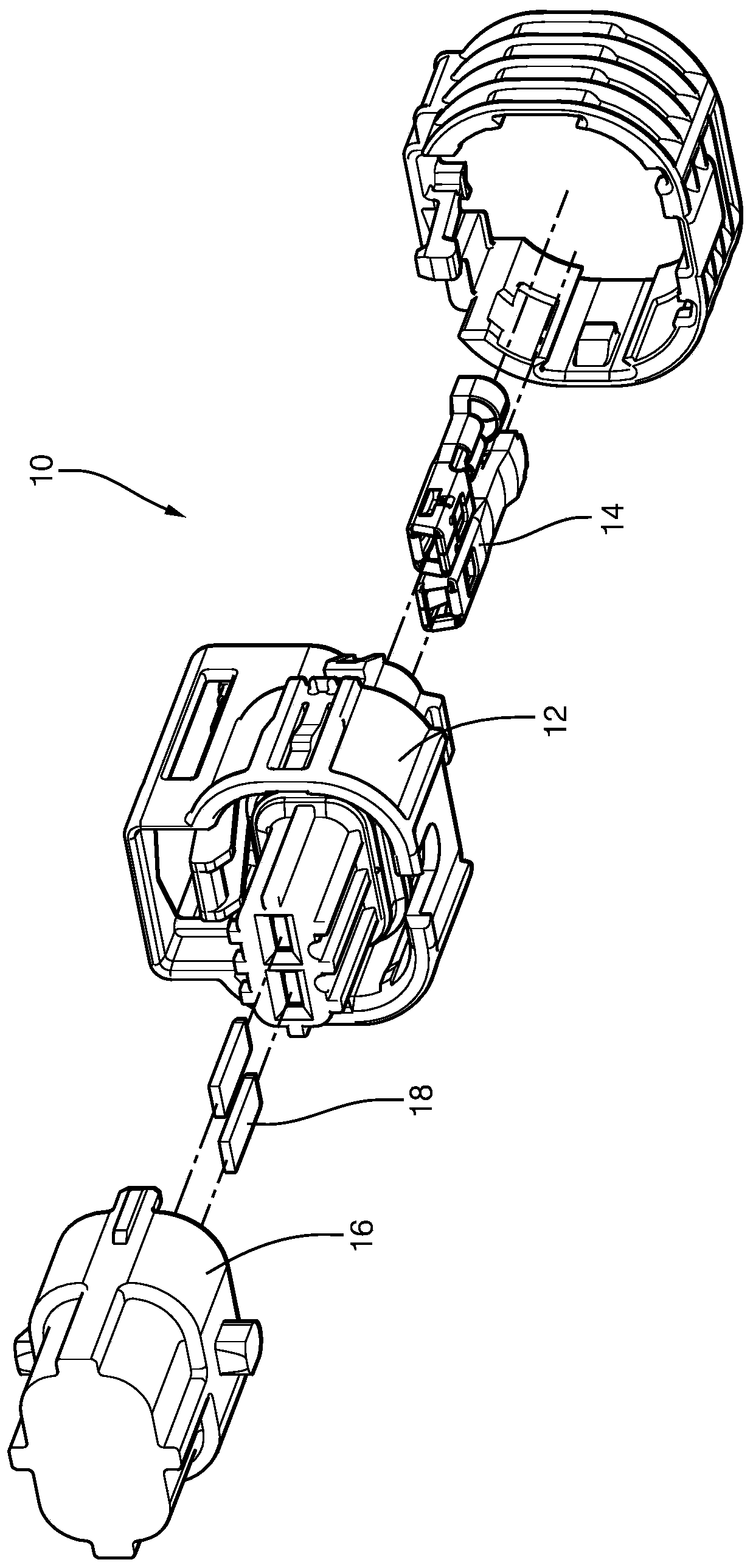
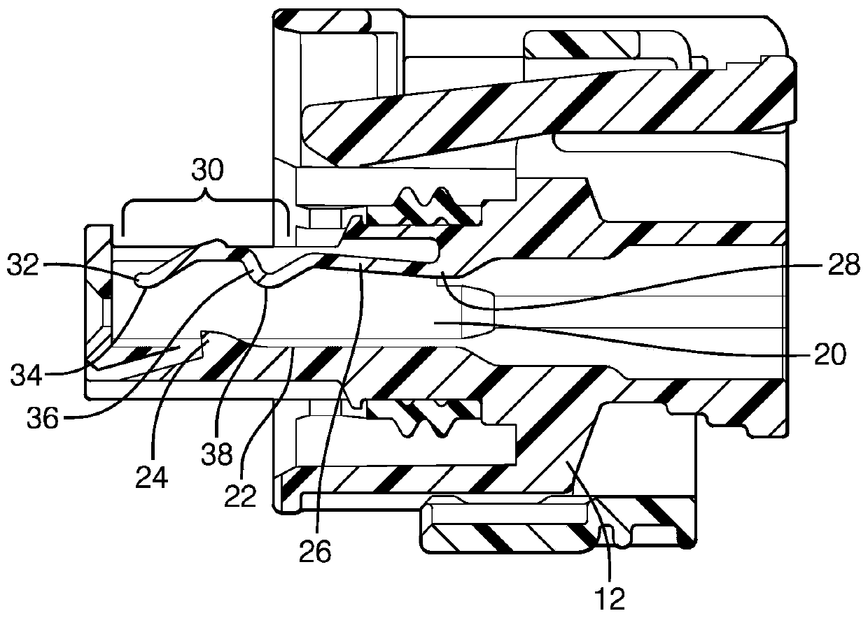
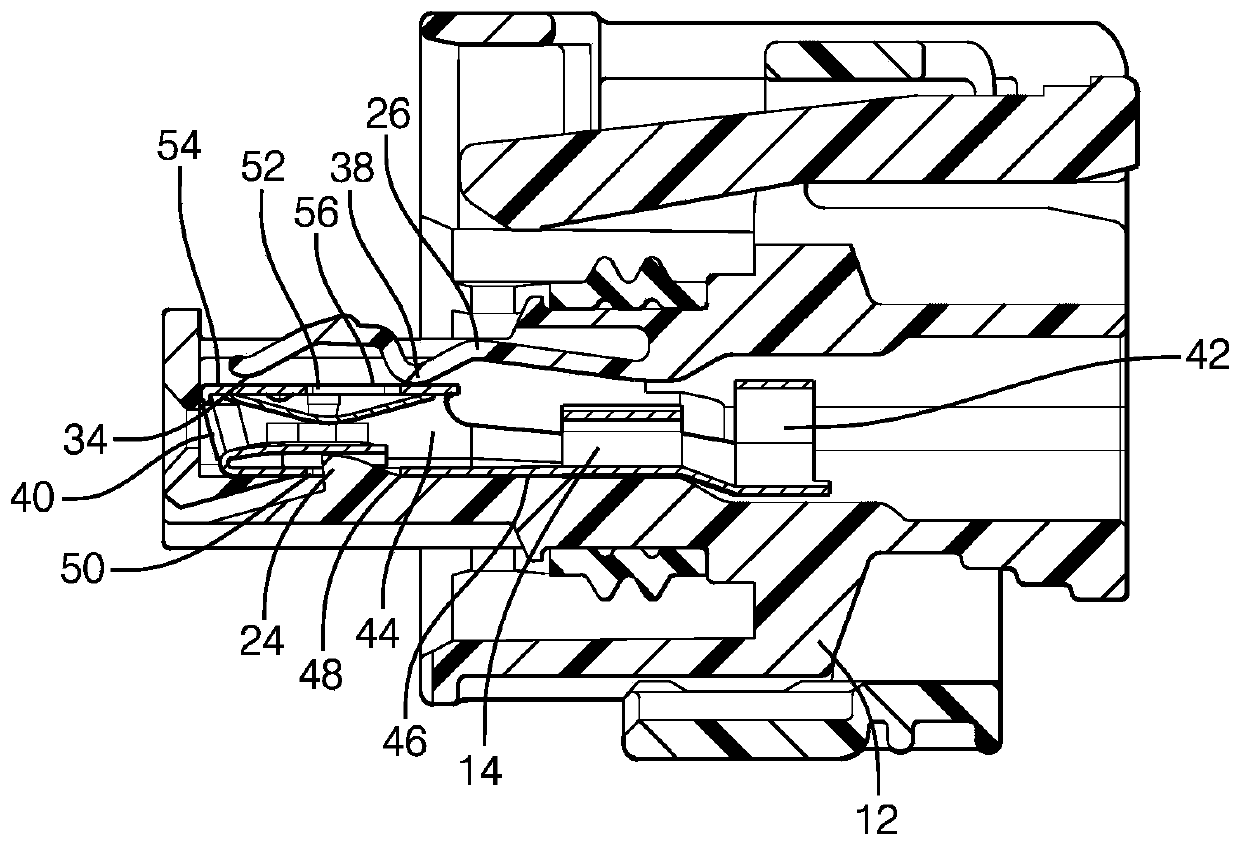
[0028] The electrical connector system described herein includes a terminal restraint beam configured to apply a spring force to a terminal disposed within a terminal cavity of the first connector body to maintain engagement of the terminal with the terminal locking prong, the engagement inhibiting the terminal out of the terminal cavity. The terminal retention beam is also configured to contact an inner surface of the shroud of the second connector body. This contact with the shroud applies an additional force to the terminal restraint beam which holds the terminal against the floor of the terminal cavity, thereby inhibiting vibration-induced relative movement between the terminal and the terminal cavity.

[0029] In the following description, terms describing orientation such as "longitudinal" will refer to the fitting axis X, while "transverse" should be understood to mean an axis perpendicular to the fitting axis X, which is not necessarily a transverse axis. Furthermore,...


PUM


Abstract

An electrical connector system (10) includes a first locking tip (24) extending from a base plate (22) into a terminal cavity (20) and a flexible member (26) overlying the base plate (22). connector (12). The beam (26) has two terminal securing protrusions (34) extending into the terminal receiving cavity (20). The electrical connector system (10) also includes a terminal (14) having a locking edge (50). The terminal (14) is accommodated in the terminal cavity (20) such that the retaining protrusion (34) engages the top surface (52) of the terminal (14) to apply force to the terminal (14) A force biased towards said rigid base plate (22). The locking tip (24) is engaged with the locking edge (50), thereby preventing the terminal (14) from being unintentionally withdrawn from the terminal cavity (20). The second connector (16) defines a shroud (60) into which a portion of the first connector (12) is inserted, wherein the beam (26) compressively contacts the second connector (16) inner surface (62), thereby further increasing the force applied to said terminal (14). The connectors (14, 16) may be formed by an additive manufacturing process.

Description

[0001] Cross References to Related Applications [0002] This application claims the benefit of priority to U.S. Patent Application No. 15 / 414701 filed January 25, 2017. technical field [0003] The present invention relates generally to electrical connector systems, and more particularly, to electrical connector systems having terminals retained within terminal receiving cavities of a connector body. Background technique [0004] It is common in the prior art to provide electrical connectors having terminals received in terminal cavities of the connector body. The terminals may be retained in the connector body by flexible locking tangs or fingers. Flexible locking tangs or fingers may be formed as part of the terminal or connector body. Terminals with flexible locking tangs or fingers are complex structures to manufacture, tend to have at least two separate parts to be assembled, and tend to be large and bulky. Similarly, connector bodies with flexible locking tangs or ...

Claims


Application Information

Patent Timeline
Patent Type & Authority Patents(China)
IPC IPC(8): H01R13/02H01R13/422H01R13/46H01R24/00
CPCH01R13/02H01R13/4223H01R13/46H01R24/00H01R13/4226H01R13/639
Inventor J·R·莫雷略J·M·雷尼G·A·小莱因哈特
Owner DELPHI TECH INC
Features
  • R&D
  • Intellectual Property
  • Life Sciences
  • Materials
  • Tech Scout
  • Unparalleled Data Quality
  • Higher Quality Content
  • 60% Fewer Hallucinations
Learn More